
We obtained recently an exceptionally rare device
Askania Kinotheodolit Kth 41
(Kino-Theodolit)
Though, whether this concerned a post-war modification is not yet clear to me.
Page has been initiated on 11 September 2021
Current Status: 29 April 2022
Update: 2
Update: 3
Update: 4
Update: 5
Update: 6
What was the purpose of a Kinotheodolit?
Imagine:
When, or example, at Peenemünde, or in post-war America - experimental rockets were launched - it is essential to trace the trajectory up to a considerable height.
Two man on both sides were controlling the actual movements.
One operator, followed the azimuth, whereas the opposite operator followed the elevation (height) of the body.
At the rear end there runs a 35 mm film registrations the both fore called parameters, but also the image of the launched body was optically recorded on that movie film.
We do not yet possess any form of documentation.
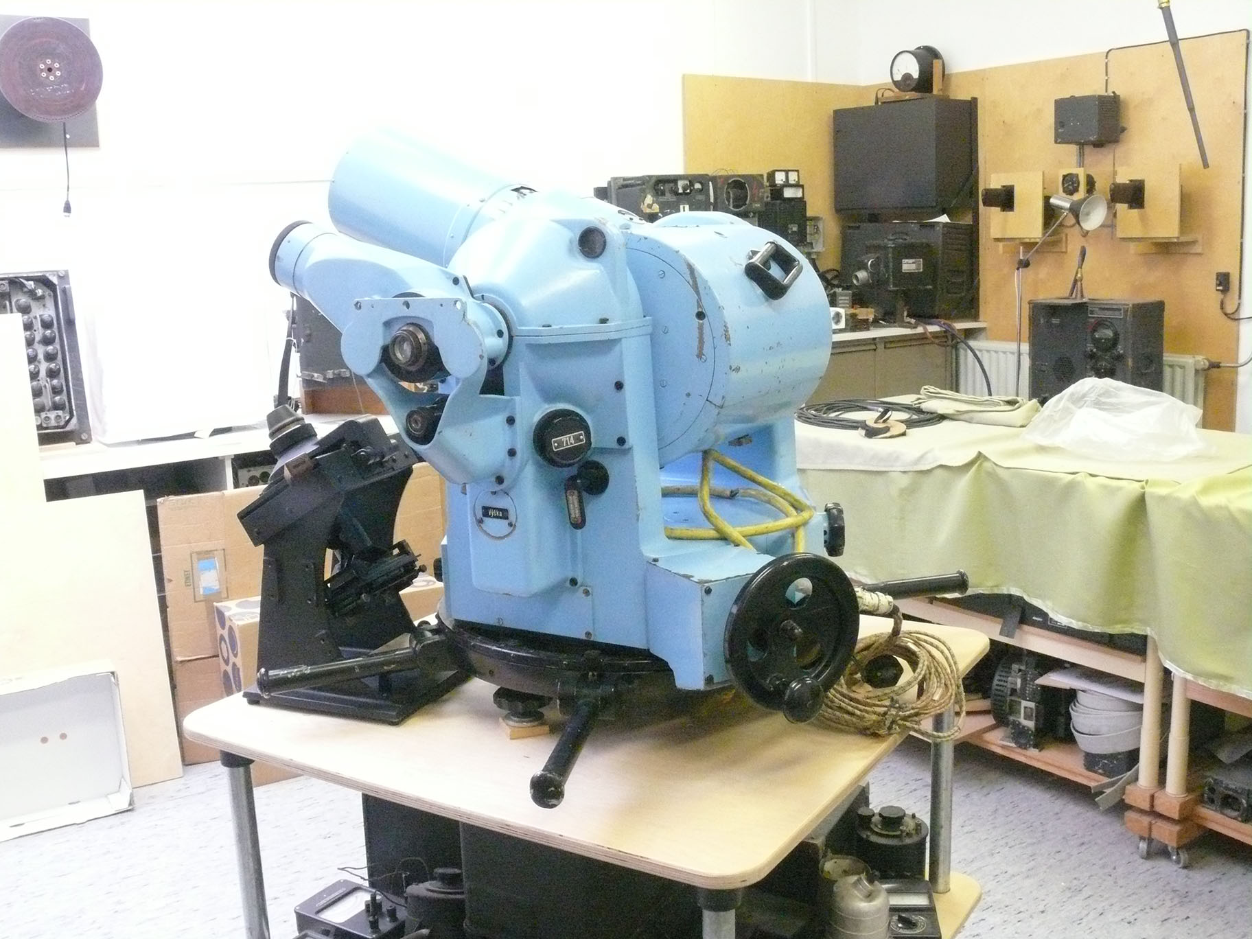
Our apparatus just arrived, and being moved to our rear exhibition room
The big lens, had been disconnected during transport as were some other parts.

We have to apologise for Marc's movement during the hectic of events
In front a film measuring viewer

In the background Anton Kroes, whom especially came over the support us, because we guess this bulky device weights perhaps some 80 kg!

The lens covers have been taken off

Myself, not often photographed

The unit designated Kth 41 stood for Kino-Theodolit 41 might point at the year of its introduction; likely serial number 43
The two wooden handles left and right cause up-down and left-right movement of the film section viewed at.

bxx tells us that the manufacturer was Askania
The white plate is explaining the consequences of the two handle movements.
Inside the curved rear section are mounted the film two cassettes (one exposed and one un-exposed)
What I have not yet find out that, is, as far as found on the web; is, that the elevation controlling operator also had the secure the correct distance focus of the big lens in the centre.
But, how I don't know yet. What might hamper us, is, that in non-operational condition the optical section in the rear being shut-off from the image passing though the big lens.
Continuing on 14 September 2021 with contribution 2

Viewing again in a bit increased detail our Askania Kinotheodolit
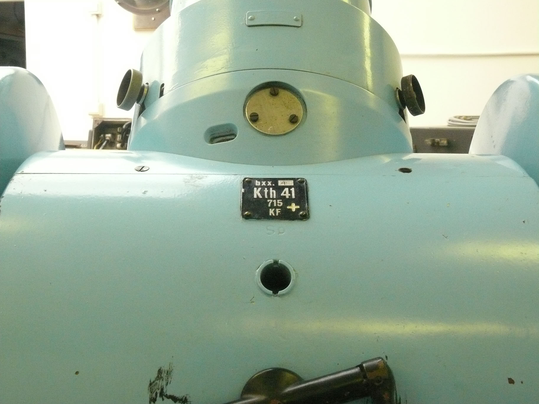
bxx 4 (Askania; likely serial number 4)
Kth 41 (Kinotheodolit type 41, which value might also be related to the year of its introduction, thus 1941)
715 (likely a number used during manufacture, as on the next photo - which shows the rectangular blue/grey plate from a different angle)

When you look at it carefully, you will also recognise the number 715 as is noticed on the foregoing type number plate
Looking upward we notice the figures 4,5 6,3 constituting the regular logarithmic diaphragm value.
First we learn that the maximal lens opening is diaphragm 4,5

I have to apologise for the over-exposed light reflecting in our camera lens
Viewing inside the film recording compartment
Please notice the two tubes left and right from the centre section.
The data of elevation and azimuth have to be recorded together with the image of the monitored rocket launch.
As analysis can only be maintained when all concerned parameters and the image are exactly coinciding.

The rod on the right-hand side is pointing at the tube through which the light-beam containing the azimuth data (value or figure)
Through both tubes are the optical angular data of azimuth and elevation projected at the according cine-film frames

Now pointing at the tube through which the light beam containing the data of the system elevation; as to provide after reflection, likely through a prism also these data on the film strip
Used was 35 mm a regular film size even for movie cinema.

All these figure were in those days used in connection with camera lens diaphragms

A quite nice image from the diaphragm setting and the showing also the way the lens being fixed onto the main body
Lens Serial number: 340766

Albeit that I am not acquainted with Czech language, the switch is selecting either between the Din sensitivity value of 16° or 21°
Regularly this section being screened-off by means of a lid.
YouTube films:
Film 00088: Viewing the newly obtained Askania Kinotheodolite. Such apparatus had been used, for example, in Peenemuende and after the war also in the US, recording experimental rocket launching.
Film 00089: Now we are viewing the 35 mm film recording cabin. Also is shown how the Azimuth and Elevation data being optically added onto the recording fil-strip.
(3)
Clive Kidd, did send me, very kindly, some hyperlinks of which he consider I might know already; which actually isn't the case.
Among it a versatile like: https://apps.dtic.mil/sti/pdfs/AD0718565.pdf
AD0718565-p5
I have rotated this line drawing
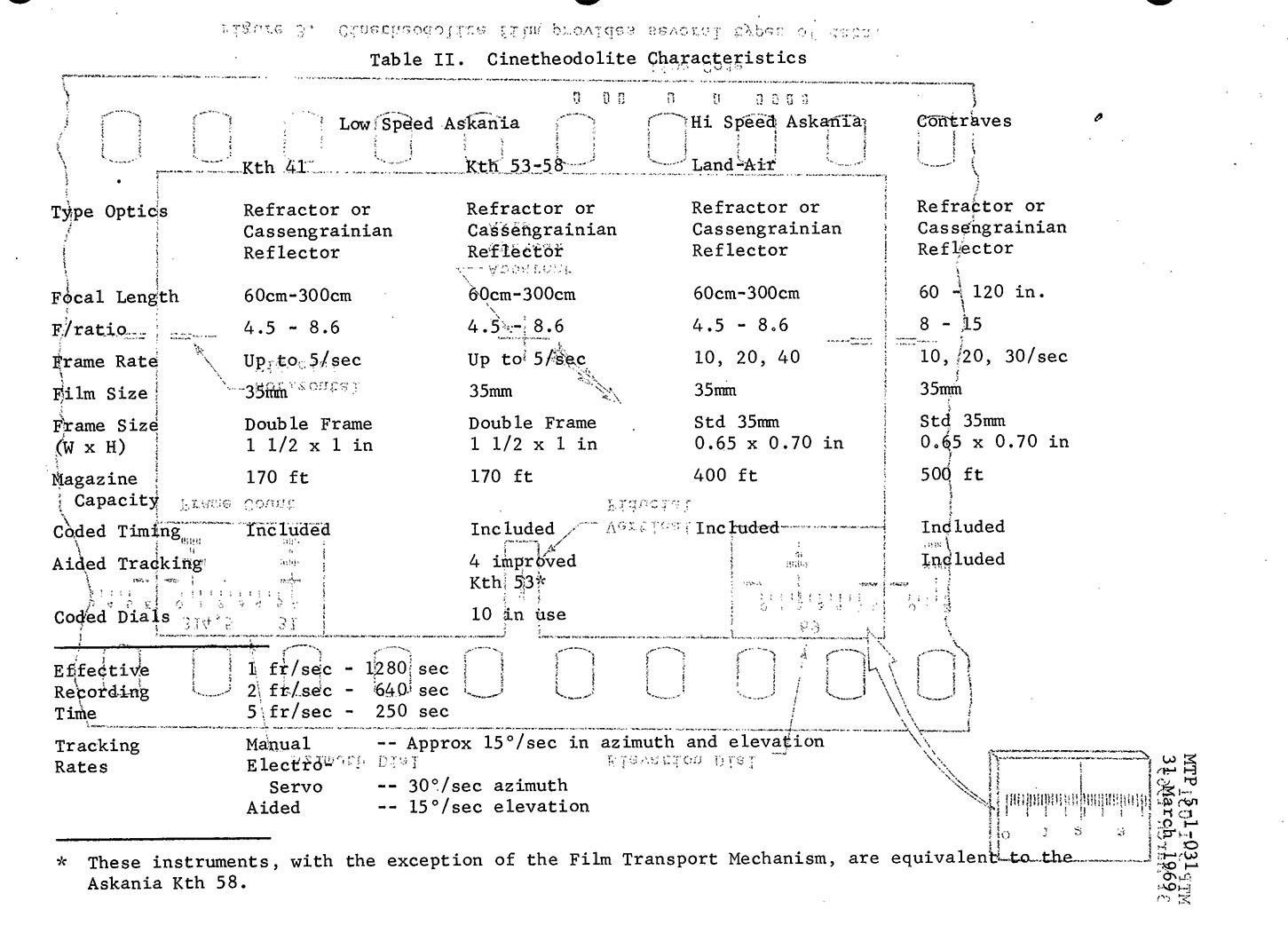
For us is the left-hand column Kth 41 of relevance
The two scales are visible down on the far right- and left-hand side
Which I have shown you at (B10) (B10return)
AD0178565-p6

I suppose that this way of 'in frame registration' originates from a different type of Kinotheodolit (however, a later document is showing that also the Askania Theodolite 41 is projecting its bearing data at the upper side of the film strip.
The essential difference is only that within the Askania Kth41 the bearing data is optically inserted now in the upper side of the cine-frame instead of as in the foregoing picture in the low frame-side.
AD0718565-p 7

Quoting:
3. Askania Cinetheodolit (Kinotheodolit).
Continual improvements in design and long life construction have perpetuated the Askania family of cinetheodolites. Low speed and high speed instruments are available. The low speed Askanias use a pulse operated intermittent film transport mechanism with frame rates of up to five per second. (Hence, our Kth41 type is of this latter type) The high speed instrument uses a cine-type mechanism: The film is in constant motion past the driving sprockets and pauses only long enough at the aperture for exposure. The high speed unit can be synchronised to run to run at rates of 10, 20, or 40 frames per second. Table II gives characteristics of Askania instruments in actual use at a missile range. (A typical model .....) This four functional sub systems; the camera-optical system, the tracking system, the angle-recording system, and the timing synchronizing system.
AD0718565-p9 quoting:

The camera-optical system includes the objective, shutter mechanism, film gate, film transport mechanism, and frame counters. The objectives are chosen for each specific type of test, and can vary between 30 and 300 cm focal length. The 60 and 120 cm focal length lenses are the most common., The main shutter mechanism consists of overlapping vanes. A maximum pulsed rate of ten exposures per second is permitted at durations of 1/150 to 1/200 second. The film magazine will hold up to 110 feet (35.5 m) of 35 mm film.
The tracking system of the Askania design places the camera within the central drum or main barrel which carries the optical system in elevation. The camera is thus maintained fixed in relationship to the telescope. Attached to the trunnion shaft so they remain parallel to the telescope axis are the sighting telescopes. Each sighting telescope on the target image by adjusting the elevation and azimuth controls.
The angle-recording system consists of separate optical trains and synchronised high intensity flash lamps which effect photography of graduated glass scaled on the upper (or lower) corners of each film frame. Reticles in the optical trains provide for reading to minutes of arc or the hundredths of a degree. Synchronised flash lamp illumination assures precise time of dial recording, and prevents blurring of the dial image due to tracing motion.
The timing synchronizing system controls shtter timing and dial flash lamp illumination. The synchronizing system is actuated by electrical code pulse received from a centralized timing control station (not in our situation) The inherent delay in the shutter mechanism is reflected in the advance of the shutter command pulse ahead of the dial flash lamp pulse. .....
AD0718565-p 12, quoting:

Tracking Distance.
Accurate prediction of the detection capabilities of cinetheodolites requires a very detailed analysis. However, for general information it can be said that the distance at which cinetheodolite can successfully record an object is a function of three major parameters (see below). The first is the minimum size of image film plane that can be tolerated. Normally this is approximately 0,004 inch (0.1016 mm). The second is the focal length, f. The third is the least dimension, i, of the subject.
For further information please consider the above notice integral AD0718565 hyperlink.
As to get an impression and understanding for the deviation cause mechanically and through, for instance, environment

Thermal & mechanical deflections in the mount are functions of basic design configurations & rigidity
In my perception, this line drawing is explaining the (angular) deviations which are being caused by the various errors.

Another aspect is, for example, the Azimuth Error Δ A


The limiting factors are the Atmospheric Factors
Visibility.
Optical instrumentation may be compromised by fog, haze, smoke, dust, clouds, precipitation, or failure of the target from different directions as time of the day (including the according refraction values) and target position change. Reflections from the target to the optical instrument change constantly with the target aspect and angle of illumination. brightness of the sky in the background changes with the time of the day, atmospheric conditions, and the direction of the line of sight. The brightness of certain typres of paint may very with the angle of light incidence. All these variables constitute to a wide variation of optical visibility.
Contrast.
Contrast depends on the brightness of the background and the brightness of the target at zero distance and vice versa. In cinetheodolite work, a condition of zero distance does not exist; therefore, as target distance increases contrast is reduced by the combined effects of atmospheric scattering, atmospheric absorption, contrast transmittance of the atmosphere, and the contrast threshold of the observer (operator). At near distance, the image of the target reveals details of shape. At some greater distance, the target image is merely the diffraction pattern of a point source. As a rule-of-thumb minimum brightness of twice the brightness of the background to the target or vice versa is necessary for successful cinetheodolite instrumentation.
Greatly dependent on contrast, the minimum acceptable image size is a matter of local definition. Film grain size, other objects in the background, change in image position from the frame to frame, the needs of particular types of instrument, and personal qualifications of the film reader affect the image size required for positive identification. However, a diameter of not less than 0.004 inch (0.1016 mm) is considered generally acceptable by film reading personnel; while an image diameter of than 0.001 (0.0254 mm) is not likely to be satisfactory.
Let us consider finally the deviation errors due to refraction

Effect of Refraction (due to the fact the when an electro-magnetic wave, thus also light rays, passes through the barrier of different dielectrics the light rays being deflected) on Virtual versus True Target Positions, Seen from a Single instrument
(4)

The entire file source: https://www.asprs.org/wp-content/uploads/pers/1952journal/sep/1952_sep_686-692.pdf
For your convenience directly in PDF
(5)

Front-cover of L.Dv.T.1454/1
Kinotheodolit
und Kinotheodolit-Auswertegerät
Kth-41
Oktober 1941

Askania-Kinotheodolit auf Gestell
(6)

Zeichnung 2 (Drawing 2) Kinotheodolit-Schnittzeichnung
Please click at this drawing as to open it in pdf, now being modified!
Viewing it PDF allows you to study this magnificent apparatus and its optical system in greater details

Abb.3. Kinotheodolit der Höhenseite

Abb 4. Kinotheodolit der Seitenrichtseite

Abb 5. Linsen- und Spiegellinsen-Hauptfernrohr
The lens is based upon a mirror section at its end (towards the film cassette)

Abb. 6. Kinokammer auf Montagegestell
Abb 7. Kinokammer, Getriebeseite
Please click at this drawing as to open it in pdf

Abb.8 Kinikammer, Kassettenseite
Abb. 9. Kinokammer mit Justierfenster und Lupe
Please click at this drawing as to open it in pdf

Zeichnung 10. Schaltplan der Kinotheodolit-Meßstation
Please click at this drawing as to open it in pdf

Abb.17. Kinotheodolit im (Transport-)Kasten
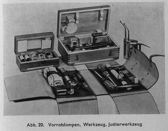
Abb.20. Vorratslampen, Werkzeug. Justierwerkzeug
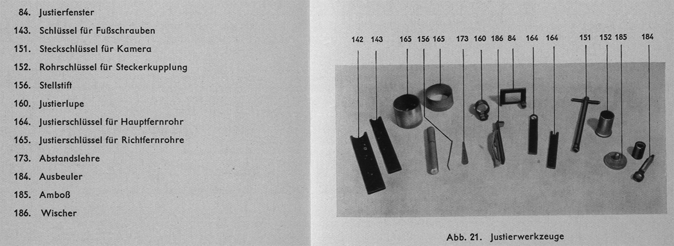
Abb.21. Justierwerkzeuge

Abb. 22. Auswertung des Filmbildes
Please click at this drawing as to open it in pdf
You might not recognise this device but, ours is shown below
To be continued in due course, Deo volente
Those whom would like to share or contribute, please contact us at:
![]()
Please type in what you read
By Arthur O. Bauer
![]()