
This new webpage has been introduced for practical reasons, namely:
Our 'details 2' page is becoming too slow for many of our visitors
and
It is not practical that a page contains more than 110 photos. Down loading might sometimes taking too much time.
For your own convenience, we would like to advice you to use the search mode window
for Windows users: Ctr + F
and for Mac OS X users: Cmd + F
Entre your particular search word and all those words inside this document will be successively shown
Started on 14 June 2011
State of affairs: 5 February 2012
About a decade ago Jan Eshuis gave me this cable-end with its accompanied female connector
He later, luckily, gave me the rest of the full cable bundle comprising of, I guess, 10 to 15 meter with attached connector. Quite heavy stuff by the way!

Shown is a Siemens & Halske (S&H) female connector belonging to the 30 core signal cable shown previously. Whether this connector is of the so-called 'Renk-Stecker type' I cannot judge
I guess, that these kinds of cables had been employed for Flak or search light systems. On both sides of the cable they used female connectors. I believe that this was handsome because it was always guaranteed that the cable is always fitting onto the system connectors. The copper cores are quite heavy and, as Buna had been used, the rubber insulation and cable cover is still in sound condition. Buna was (is) a synthetic rubber which enabled the Germans to come around the lack of natural rubber supply. It was invented and mainly produced by IG Farbenindustrie. By the way, IG Farbenindustrie had quite strong commercial contacts within the US, and the main Buna patent applications and techniques had been sold to the US in the 1930s.
On 1 June our attention is being focussed this time towards items on display at our "Rarity Cabinet".
The first device is normally covered in a closed box.

An old fashioned photocell
This device might have been meant for early low definition TV. It was purchased at the Hoenderloo market, some years ago. The photocell is in a wonderful condition and I have never seen such one before. Whether it is a high vacuum or gas filled type I don't know.

It was manufactured by Pressler of Leipzig
The Ni tubular connection is connected onto the photocell surface (electrode). The second electrode is visible down the Bakelite tube.

Photozelle Original Pressler
Please look for details on the Pressler Company at: http://www.crtsite.com. Their main products were neon voltage regulators (Stabilisatoren).
Another intriguing item is shown next

An interval counter
I do not entirely understand where it had been meant for.

The sequence counter might indicate the number of intervals
The two small circular disks up and down the mechanical counter is to set (reset) the counter position.

Production or acceptance date: ('Tag') 10 October 1941. Serial number 249?

The base probably is not meant to be connected onto, as the real soldering tags are on the left hand side

We do not understand why the mechanical sequence counter is being screened-off this way. Maybe for environmental reasons
Next

Biax or Twinax connector (a symmetrical or dual core screened HF cable-connector)

Brechkupplung
This connector is having the same features as is having the well know Brechkupplung used for the aircraft communication systems (like FuG10). When we have visitors in our museum, I quite often show them the technique used for the head-phone-set of aircrew. It is evident, that when there is emergency that every obstruction by leaving aircraft is most dangerous. In effect, the connector is strongly resisting pulling in line with the connector. However, when a weak force is acting at the connector under even a slight angle the plug releases most easily. One have to think, I guess, that their force ratio is 1 : 25 - 50. It is always intriguing seeing the face of those doing the experiment. They cannot believe what they just have experienced! The trick is the way the male pins are being designed (shaped) in conjunction with the possibility of the female section in widening its tubular diameter when out-of-line force is being encountered (spring-loaded). However, it is not responding upon strong vibration forces. Really ingenuous!

The major parts of which the connector is being build
Next

An aircraft cable connector
It was, like so many other 'edge' connectors designed by "List".
It has to be noticed - that the knowledge and applications of the so called 'edge connectors' originate from German design. That these were later adopted in the US is well known. But, that it was a typical German design is not well appreciated! I could never trace a patent, and this might indicate, although I actually cannot yet prove it, that the patents have been kept hidden in the U.S. for practical reasons (trophy of war). Similarly is the case with the coaxial-cable-connector which later became the well known as a "F-Connector" used in modern satellite receiving systems. Please consider my German Airborne Radar paper at page number 15. Then you will understand what it is about. Please notice also our patent reference dBase page, and read the introduction - you will grasp my point.

Fl 32 109-2
According Peter Aichners book "Luftwaffe Flugzeug-Ausrüstungsgeräte, Band FA/01" (1997) it was introduced in 1941.
Please notice the "List" manufacture symbol! I guess, that Russian copies might be here and there around. Although, I have never seen them. I might have obtained this device from Ebbe Pedersen in the 1970s.

Unknown antenna stub, indicated with: GP/N
I guess that it might have been used in big arrays, such as Mammut or equal phased array systems

The Al end-nut has been removed and a tuning arrangement is becoming visible

The tuning dial is set at number 15
It is not jumping in numbers but linearly moving. This could mean that a spiral could be involved inside, which might point in lower frequency operation

The coaxial connector

Wobbel motor 'Mo 1' of the Gemse receiver (IFF)
On the left the power connections and on the right hand side the capacitive tuning

The wobbel motor is of the Ferraris type, which needs two phase power, like is used in mechanical house hold power metering
On 9 June 2011 some more devices from our 'Rariteitenkabinet' have been added

Quartz thermostat
Sadly the glass Dewaer-container inside is broken about three decades ago, as our cat 'Pietertje'* walked at the quite narrow shelf where it was standing on display. She was not to blame! In all those years this might have been the only item that was affected by her. * Photo taken early 1970s, when we lived in the very hart of down town Amsterdam, about 200 metres from the Dam Square. What an exciting time!

Inside the thermostat is mounted a 9500 kHz quartz crystal made by Radio Loewe A.G. D.S. Loewe
This might indicate that it might have been before 1938. Loewe was already engaged in quartz crystal manufacture from about mid 1920s onwards. I guess that it was meant for the use in a shortwave transmitter. The green resistor is heating up the system. Notice also the glass-wool application.

The two green heating resistors are visible.
On the right inside the black shielding is the bi-metal temperature controlling device. I guess, that the black shield around it is to screen the switching pulses off the quartz crystal.

The contact socket. Its shape is like the European valve base but than bigger
Let us consider closer smaller components

For this occasion I have dismantled a Lorenz low frequency iron-dust core
It is noticeable that it is of quite elaborate design. The rod like device on the far left is as to fine tune (adjusting) the coil inductance.

Two in capacitance equal block Cs
On the right the high quality version, where the capacitor a thoroughly screened off from environment by means of ceramic/soldering technique. Expensive, but even after say 70 years performing as if it is a new device. However, the left one is the quality standard of about early 1943 onwards. Far more simple and thus cheaper to be manufactured. The type, like the American and maybe British ones, they are not entirely sealed off from environment; suffering from hydroscopic effects. They often are causing circuit failures.

Combined capacitor block belonging to the 100 WS
I guess that the contact stand-offs are being soldered, so that environment is not having effect on its quality. Although, I haven't checked it. It carried Lorenz part number Sk557801. It actually was manufactured by ERO (well known in post war years). I also have seen ones manufactured by Hydra (owned by AEG).

DIN 99815 type antenna connector set
Mainly used by the German Navy (KM) and often Lorenz sets used it. DIN means: Deutsche Industrienorm or accordingly: German Industrial Standard

DIN 99815 connectors (male and female)

Side view of the standard naval connector

DIN 99815 female connector dismantled

Antenna inputs of our Lo6K39
One is to be used for the outdoor antenna, the second one is connected with the transmitter room. So that it becomes possible to listen into the signal of the transmitter oscillator stage. Thus without the necessity to transmit.

KJ 131 N 2/38 AEG Telefunken number 24510
Telefunken pre-war blind-landing system. It consisted of at least three moving coil sections. The square in the centre is also connected to a movable system, which changes between red - black - green. When I remember well, this device might have been obtained from Ebbe Pedersen in the 1970s.

The square in the centre (red - black - green) is illuminated. The tiny lamp with its holder is pushed inside the meter module

Kurszeiger (Left - Centre -Right indicator)

Kurszeiger LKz 3 (belonging to gyro systems)
Bauart Siemens - LGW
Gerät-Nr. 127-211 A-1 (actally production drawing number)
Werk-Nr 699941 (this production number is been coded, maybe serial number 641 or 941 (who knows)
Anforderz. Fl 22562 (GAF Stock number)
Lieferer: Luftfahrtgerätewerke Hakenfelde GMBH (= LGW)

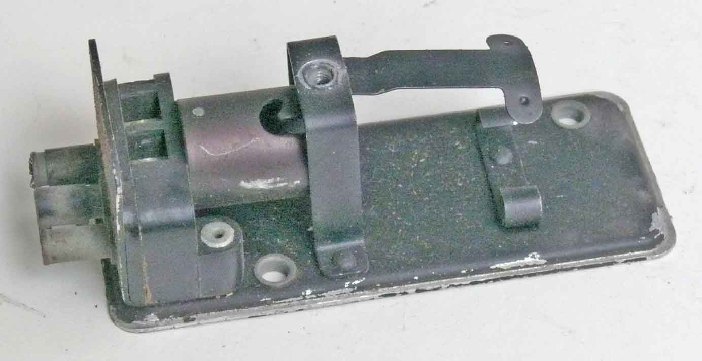
Verzögerungsschalter VS2B/2
Bauart - Gerät-Nr. 102-91.10
Werknummer (not given) 24 V

Delayed-relay, internally viewed from the right-hand side

The left-hand side of the delay-relay
The circular housing is covering an electrical motor. The switching-contacts are shown down on the far right.

Gerät-Nr. BM. VS 2B/2
In my perception the Germans showed a lot of ingenuity in their connector designs.

So-called: Waffenstecker. Although, it might have been called differently
This connector is full of interesting aspects. Very easy to be connected/disconnected. By simply pulling the left flap leftwards

The spring loaded flap/cover had for this occasion to be pulled downwards as to allow seeing the silvered contact types

The chassis section as its connects are being protected by the spring loaded metal cover

The six silvered connector contacts are clearly visible.
Interesting is that these contact do rub against the chassis contacts for just a few mm, which is clearly visible, as there is no oxidation at the contact sections. The two holes in the chassis connector is to be meant to stag several connectors.

The connector is not yet being locked

There existed connector versions for: 1 - 2 - 4 - 6 - 8 and 10 contacts. Shown is the 2 contact version

The two-contact cable connector

The Berlin radar used these so-called Waffenstecker as well. Shown is the left-hand side of the Berlin radar PPI (SG224)
There are strong indications that this connector, at least from late 1943 onwards, where becoming a standard connector. Their advantage was, simplicity - robustness totally inherent to extremely strong vibrations, most simple to connect and disconnect - ascertaining that contacts do clean themselves just before being fixed.

Naxos system Antriebsverdrosselung 350?
Ln29449 (GAF Stocknumber)
Werk Nr. 175150 (Serial number) which number is being coded. This HF noise suppressing filter is used in aircraft. It was placed in between the 24 V (29 V) aircraft power system and the Naxos antenna-motor.

I guess, this is the side that is to be linked with the antenna motor

I guess, that this side is connected onto the 24 V (29 V) aircraft power system
Please notice the hermetically sealed-off blocking capacitors.
The Naxos antenna-motor (aircraft version) used dc and hence, had to employ collector brushes, which will generate RF noise spectra. That is why an additional filtering was necessitated.
The next component arrangement may be regarded being one of the most ingenious concepts in the field of transmitters! Of course, viewed from the perspectives of the 1940s.

Shown is the dynamic frequency stabilisation circuit of the FuG10 aircraft system

On the far right inside the white porcelain cylinder is C 5a (hermetically sealed-off)
In our patent dbase I call it C5, as this is what it is designated in the FuG10 manuals.

The spectacular module seen from a slightly different perspective

Viewing the module again from a different angle, as well

The frequency stabilising arrangement of the FuG10 system

The interconnections underneath the ceramic base plate
Why have I bothered you with showing this device. Because it is a landmark in HF transmitter design! 'TK' might stand for: Temperaturkompensation or Temperaturkoeffizient.
It was already known that frequency compensation could be achieved by means of temperature controlled circuit design. Eventually by means of special temperature controlled capacitors. The Germans used in 99.9 % of all their circuit designs "oscillator" keying. Hence, transmitters were fully blocked in all transmitter stages. For simplicity, they used mainly power valves in the oscillator stage, as to get enough driving power for the final amplifier (in the PA stage). When a valve, particularly power valves, starts up operating the anode will become heated due to energy dissipation. When the anode is starting to dissipate, it will change its static capacitances (Cga and Cgk) (neglecting the dynamic aspects). Most of German wireless communications ran by means of Morse signals. Their content is always quasi erratically changing. When the transmission stops, it takes some time before the anode have been cooled down. It is understandable that under these conditions temperature compensation never is to follow the actual dynamic state of affairs. The increased temperature might reach the compensating circuit even after transmission had been stopped. The clever idea was: to integrate some ceramic capacitors having strong dielectric loss in combination with a particular temperature coefficient. When HF is being supplied on to them, they will directly respond by internally heating up. The parameters of the transmitter valves incorporated and other circuit values are known. It becomes now possible to dimensioning these loss having capacitors such - that these dynamically respond in a manner that these compensate the static changes of valve capacitance during operation. It was possible to achieve a system temperature response of 5 ppm / K, which is extremely good for a MOPA transmitter concept.

Shown is the original drawing page of patent: DE761260. Application date 24 December 1940. Granted 7 December 1944
For detailed information click at the original patent file: DE761260
That the above patent drawing differs a bit from our photos might be due to practical reasons, as the circuit layout might have been improved in the meantime.

Unknown connector system

The chassis male and coaxial like female connector
It might even that these connectors are not originating from the Germans. However, I might have obtained them from Ebbe Pedersen in the 1970s, and I would certainly not have taken them when he had not convinced me of its German origin. Curious is, that we seem to have at least two sets of these.

From this perspective it does not look to have a full coaxial cable structure

Fl 32269, 126-113A (drawing number)
According Peter Aichner's book 'FA/01' being a: UV-Beleuchtung 9 watt , vollständige Anlage. He gives, nevertheless, Fl32269-3 126-113A Vorschaltgerät Bordleuchte Fl32269-1
This small unit was obtained from France about 1988. I could never find the baretter as well as the UV lamp (mercury type)
Its purpose is to carry a baretter (EW 0.7 A, 17 V?) which is to be used in conjunction with UV cockpit instrumentation light. The EW acts as a current limiter.
The 'bayonet' type baretter lamp is clearly visible

Schematic of this small box

Unknown 6 pin cable connector set
It slightly does remember us to a kind of Renk like connector arrangement.

Not expected, but we seem to have at least two more sets of these

Uni-sex pin connector configuration

Cable end
We guess, that the cap-end is been lost. Although, we must have a complete set somewhere
Next is shown a test device for old aircraft wireless systems

ZLK VIII
Fl27665
Zwischekopplung
It is meant for measuring voltage and currents in old type aircraft systems.

On the right P.Mst.1.
Prüfmeßstecker 9 adrig
Fl26764
The latter is enabling: current loop and voltage measurements.

Cable covers being removed
The clamps left and right is meant for fixing the adapter onto the system cables under test. To assure that the wiring is interconnected reliably.
On 6 September 2011 we continue with a most curious device
This module was once being lend out to someone and I we got it after 24 years back
I obtained it from Ebbe Pedersen about 1980. We know thus that it originated from Denmark. Considering the rather solid construction its use should have been in the field of Radar
We only know, that it is a coaxial joint, most likely used somewhere in the radar field. I guess its weight being 10 - 20 kg!
Intriguing is, that in contrast to German military practice it is not carrying a serial neither a stock number

The coax-connector is typical German, but its threat is just a tiny bit different

The right section side is rotatable

Looking from a different perspective

Cover plate being removed. The black ring is made of rubber, which is , after at least sixty six years, still flexible

The central rotatable unit being pulled out
It is clear that much effort is put in ensuring proper HF contact. It is also evident, that it is not meant for constant rotation as there is no provision for it, however, there must be roll bearings somewhere inside; though not visible. I guess, that it was used as to facilitate antenna azimuth bearing or elevation. In the centre we see a transparent plastic tube, probably preventing HT arcs. This might indicate that high power could have been involved.

Shown is the rotatable plunger
Watching the centre contacts we may conclude that once rather high currents have been flown through it

For explication I have put the insulating plastic tube inside

Inside view of the electrical contact section

Finally, the coaxial joint is being put a bit inside again
Is there perhaps someone around who could lift the secrecy about this mysterious coaxial device?
Please contact us at:
![]()
Please type in what you read
On 11 September 2011 we have attached some more components

60 kHz quartz module. Type QL 10
This type was used in both the Telefunken receiver type LWE-a as well as in the time-base of Würzburg FuSE62/65 D. As far as I remeber, it is of the flexible bar type resonator.

This quartz type is pluggable

Please notice the wax seals

Mini potentiometer
I obtained this device from Ebbe Pedersen in the 1970s. I have, however, no sense for what application is was being built

Realising the two contacts we may assume that it constitutes a variable resistor
There, nevertheless, is an option that the Al housing is part of the potentiometer.

It is clear that the axis is having rather small diameter (28 mm)
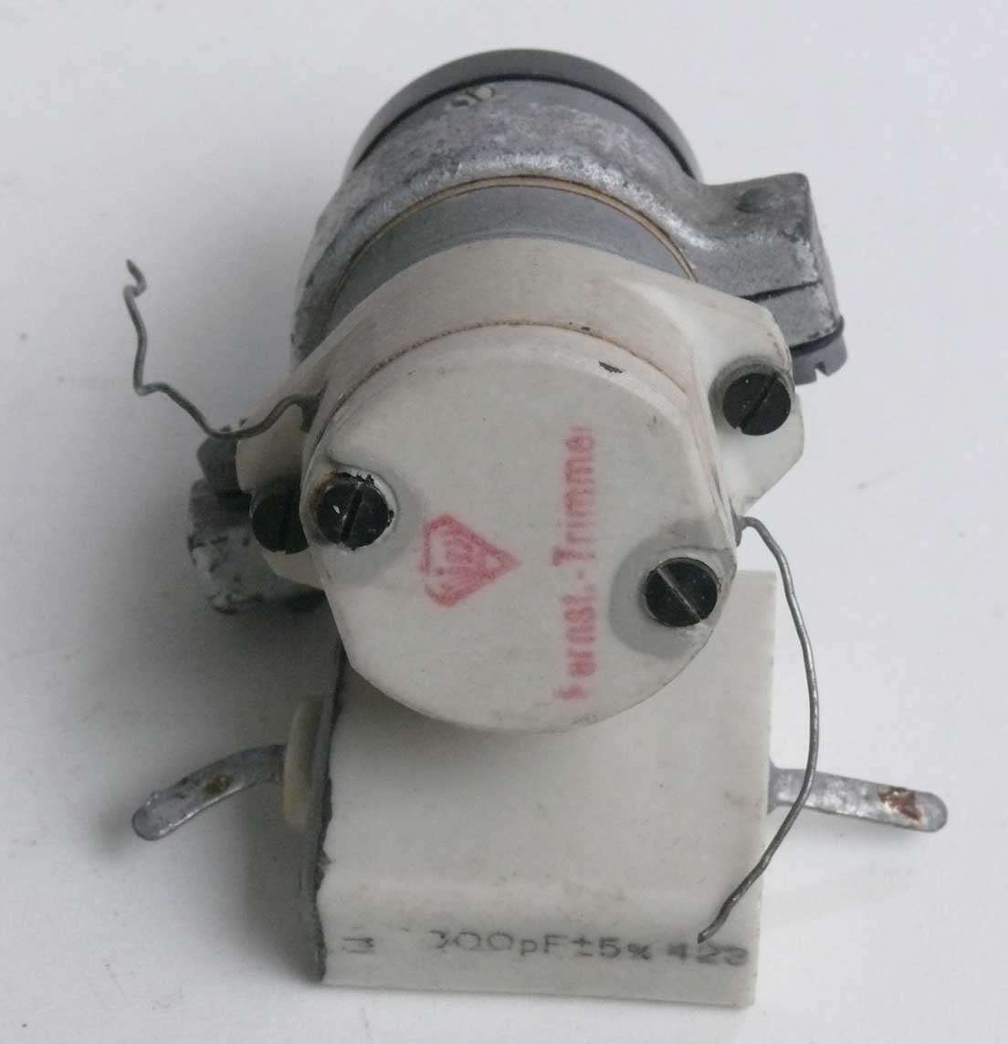
This device also originated from Ebbe Pedersen
It is the fine tuning module of Feldfu b - c - f. It is a moving coil instrument, where the moving coil is rotating a metal disk. It thus constitutes a voltage controlled trimmer (or condenser)

The principle is self-explaining
The ceramic housing constitute the HF trimmer section.

Außenluftthermometer
LNi 100 Ω
Production code pcx Luftfahrtgerätewerke Hakenfelde (LGW) belonging to Siemens & Halske (S&H)
According Funkbase Band FA/01:
Widerstandsgeber für elektr.Temperaturmessung LNi 100 Ω; Meßbereich -50 bis + 50 Grad - C Außentemperatur. (Briefly aircraft outside thermometer)
The symbol L is not familiar to me, whereas Ni stands for nickel

The two pin connector is standard for all Siemens aircraft thermometers (as far as we understand)

The quite flat streamlined section is, to my understanding, facing a bit outside the fuselage

Fl20340
The quite flat streamlined section is, to my understanding, facing a bit outside the fuselage
Elektrischer Meßbereich 0 -180 C. According to Peter Aichner's book: LNi 100 ohm. Thus its bridge resistance is also 100 ohm.

Synthetic quartz bar (raw)
This quartz bar (Quartz) was obtained from the former Philips Quartz Industry (Doetichem NL). Not visible is a very thin threat which is used during its industrial growing process. I have been once told, that it grows at about 1000° C at a pressure of 500 bar. Sometimes a growing chambers explodes with devastating result. From this bar the industry cuts quartz discs, which will be then processed.

Reisz microphone
Also known as "marble block"
This microphone was formerly used during sound transmissions from Radio Kootwijk.
On 5 February 2012 I received the following e-mail from Berthold Bosch:
Eugen Reisz war gebürtiger Budapester und schrieb seinen Namen - auch nach seinem 1913 erfolgten Wechsel nach Berlin - mit dem in Ungarn als s ausgesprochenen sz. Andere Leute in Dtschld meinten, sie sollten ihn mit dem ß beglücken. Reisz war ja einer der drei Namensgeber des LRS-Relais (verbesserte Lieben-Röhre).

The connecting side
This microphone was quite popular in the 1920s. It is a carbon type microphone. Special is, that the bias current is, not like in telephone repeaters where the bias current flows in line with the acoustical vibrations, but the current flows transversal to it. It was regarded in those days as being a high end device.
On 15 September we continued with:

"Antennenrelais" of FuG10
It is a vacuum relay. On the left is the receiver side, on the right the transmitter side.

The vacuum switch being pulled out

Viewing the contact linked onto the antenna
Hardly known is that that the Germans used TL- or fluorescent illuminations. The next device was obtained from the Bunker Diogenes (sometime called Dioganes). The huge air defence bunker of the Germans, near to Arnhem

Philips wartime TL-Starter unit (for fluorescent lights)

Philips Starter unit type: Philora Type 58404 AH/00
Its circuitry is quite self explaining.

The Philora unit
On the left is the choke the brown cylinder must be the "starter". Nowadays it is a small unit which is exchangeable from outside.

Philips Philora starter
Whether there is a combination of a small neon-bulb with integrated bimetal-contact, I don't know. /40 might indicate that it is related to the year 1940

Siemens & Halske relay type: Tstr. 0200/3
Originally coming from Radio Kootwijk in the Netherlands and was used in conjunction with station: PCH 3.

Relay opened. This type is in Germany known as: Polar-Relais

Schematic of Siemens Tastrelais type 0200/3

Its bottom mounting
It is clear that it was easily exchangable

Ln20247
Curious is, that this number cannot be found in Peter Aichner's list. According the numbers in succession, it might be part of Würzburg (FuSE62/65). But I strongly doubt this, as nowhere there is the necissity of such vertical range line (markers). I would think of FuG200 or FuG220 or that like.
Our "rariteiten" cabinet also displays: quartz crystal where under some luminous quartz (Leuchtquarze)

This type contains three quartz bars of: 3000 kHz - 3520 kHz and 4040 kHz
As to understand how they respond, please see luminous quartz
Please activate this link as to see how the luminous phenomenon looks like Photo made by Adri de Keijzer for the 2000 exhibition on "Aspecten van precisiemetingen" held in the station hall of Radio Kootwijk on 25 November 2000.

Viewing the text label, I guess that it was produced in the early days of the 1930s

Their according (exact) frequencies are provided hand written on the label

A typical Lorenz type stagged capacitor, Type KA. 13051
2265 - 2311 µµF (= pF)
These were frequently used in antenna circuits as to provide a range of taps.

The taps are clearly visible
Insulation (dielectric ε) is mica, known in Germany as "Glimmer".

Lorenz type: Stapelkondensator: 89 pF 5000 V power rate 50 KVA
According drawing number 15028
On 20 October we contributed two quite small 1920s componets

Radioaktiengesellschaft D.S. Loewe
Berlin - Steglitz
Made in Germany

Radio A.G. D.S. Loewe
VC might stand for: Vacuum capacitor

Type VC (Vacuum capacitor?)
Capacity 300 cm
Roughly 111 cm is 100 pF We may thus say about 270 pF

Side view of the small box

Loewe - Radio G.M.B.H
Berlin - Steglitz
Made in Germany
Compared with the previous box, Loewe had changed from a Ltd into a limited subsidiary of another entity. (A.G. versus G.m.b.H.)

Loewe Radio Vacuum resistor type F.Z. 128

Loewe Radio (The character L is a bit distorted)
These two components typically reflect what was state of the art of the 1920s. Most components being kept clammed, not yet soldered.
To be continued in due course
By: Arthur O. Bauer
Please proceed to, or go back to: Exhibis details
Please proceed with, or go back to: Exhibits detals 2
Please go back to, or proceed with: Exhibits details 3
![]()