
DMG 5K
Cover-name
Michael
Page initiated on 2 February 2023
Current status: 28 April 2023
Peter Hijkoop, of Middelburg was so kind to offer to us his DMG 5K code-name Michael on a long-term loan.
This most kind gesture we appreciate very much!
Please consider also the two files provided on our website:
https://www.cdvandt.org/D-Luft-T-4852-Dezimetergeraet-DMG-5K.pdf
and
https://www.cdvandt.org/DMG%205%20K-Michael-Beschr.pdf
New photos 2 (10 February 2023) Most new photos do not directly relate to the DMG 5K Michael apparatus , but, on the other hand, it is explaining more about our museum context.
So Hans Goulooze our indispensable supporter / volunteer went in Hans car to Middelburg a more than 2 hours driving.
We were welcomed in Peter's house and after a "gember bolus" and a cup of coffee we went to the bunker-site where we first enjoyed the nice exhibition.
Next to the bunker entrance in Middelburg (in the Dutch province Zeeland, not too far from Flushing (Vlissingen) we just managed to get the Michael frame outside the bunker
Due to the weight of the five modules and frame together, we have kept the plug-in modules separate.

It was a sound decision to use Han's Goulooze's car as my VW Golf would have had insufficient space for transporting everything

In front of us we notice the plug-in module number IV; the receiver module
Next to it a strange module, which apparently originated from the days the German Bundespost operated Michael apparatus on their UHF links; but they modified these sets as to cope with carrier-telephony channels.

In front the quite heavy power-supply module, designated Roman V
About ten-passed four o'clock we arrived in our Museum in Duivendrecht again.

Some of you might have noticed that one of the wheels was broken, which first had to be cured (photo taken by Anton Kroes)

The five plug-in units arrived also sound in our museum

Anton Kroes made a "selfie"
Anton Kroes on the left-hand side, myself, and on the right-hand side Hans Goulooze
The next day, Thursday 2 February I met Hans again our museum premises again

1. We first removed the side cover plates as to allow visitors to get an impression what is inside

2. First I would like to use the opportunity to get an impression what is fit at the bottom section of the DMG 5K frame

3. After having removed the rear cover plate the get a quite nice impression of the two coaxial connectors
Of which the upper one being suited for the Transmitter and the just visible lower one should connected onto the receiver module.

4. Viewing the transmitter module front and what is behind it

42. The next photographs concern the "bolometer circuitries"

5. Viewing the 'bolo-meter' arrangements
Please notice the small loop touching the cavity of the 'wave-meter' provision; and imagine that this loop enters the slit down of the loop.
The loop picks-up some of the HF energy existing when the wave-meter cavity gets in resonance due to the transmitter energy.
The two 'bolometer bridge' being fed with (suitable) mains currents and after amplification the resonance energy of the circuit being indicated on a moving-coil meter.

6. In my perception a nice photo of the two bolometer bridges
The low resistance potentiometer is to balance the bridge circuitry.

7. The right-hand side module constitutes the bolometer-signal amplifier; please view the sound vacuum capacitors component numbers C 25 and C 26
I would not wonder that after about 80 years have passed their specs will still constitute the wartime specifications.
The neatness of German high quality of German constructions is rather evident.

8. Viewing the bolometer section from a different perspective

9. It is quite evident, that the loop of the bolometer module should be put inside the wider hole in the wave-meter cavity
Let us neglect the remains of the Al-oxides.

10. The bolometer circuitry being covered again

11. Lifting a bit the cover plate of the transmitter (Osz.) module
Very sound way of securing the sound grounding of the cover-plate.

12. Isn't it a beautiful, and sound, oscillator construction?

13. Viewing it slightly differently
L3 constitutes the output-coupling of the HF energy towards the coaxial antenna connection.

14. Getting a better vision upon the pre-set click-mechanism

15. On the the left-hand side the bolometer signal out-put-stage

16. Again viewing this circuit from a different perspective
17. The power supply section is also soundly build
The two valves market STV being two neon gas voltage-stabilisers type LK 199.
All capacitors being of the so-called hermetically sealed-off types

18. Please notice the very thin variable wound resistor-wire!
Generally speaking: Luftwaffe gear was of the best quality standard the Germans manufactured!
When someone possess a genuine schematics - repairing is always rather simple - as the so-called line numbers being indicated at all ends of according cables!

19. Viewing a slightly bit differently

21. Quite strange photograph

22. The transmitter module mounted again the the Michael mainframe unit

23. Viewing the front-panel of the partially inserted transmitter module (Roman) I

24. On the left-hand side the coaxial chassis connector
On the right-hand side the Transmitter coaxial output connector.

25. Viewing the way the antenna coaxial connector is approaching the transmitter output connector

26. The Transmitter module (Roman I) being fully inserted and would, technically be operational

27. Viewing the frame from the right-hand side

28. Viewing the power-supply module (Roman) V
Rather compactly and neatly constructed.

45. Abb. 8: Übersichtsplan des Netzteiles

29. Viewing the power-supply from another side
Generally speaking - Luftwaffe (GAF) gear was built of the best quality components. Most capacitors were of the hermetically sealed-off type.

30. The front panel of the DMG 5K power-supply unit
These systems had been modified quite shortly after the war, as to facilitate the application of more communication channels.

31. It was quite common practise that transformers were provided with their windings data, including the winding-strength (wire-diameters)

32. For maintenance purposes it was possible to work on the modules by means of two 20 contacts-extension cables (one for every side of the module)

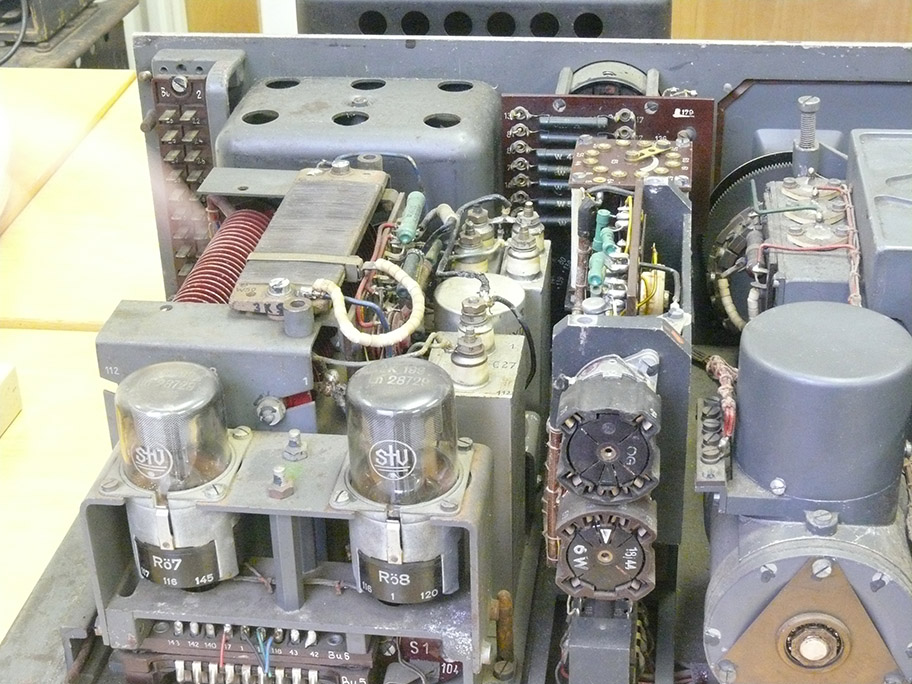
33. Signal module, WTZ meant Wechselstromzeichen (mainly FSK technology)
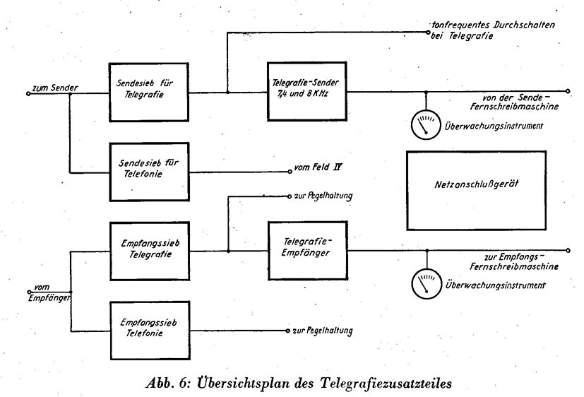
44. Abb 6: Übersicht des Telegraphiezusatzteiles (no longer functioning due to partialy scrapping)

34. It is evident that viewing it inside, that it concerns mainly scrap
(M2155 ↕↕↕↕↕↕ M2155return)

35. At least we get an impression how it once might have looked alike ↕↕↕↕↕
↕↕↕↕↕↕↕↕↕

36. It is interesting to notice that the inter-wiring commenced on the upper side of this module

46. Abb. 9: Betriebsgestell, Vorderansicht
Viewing the genuine Michael DMG 5K frame as if genuinely did look alike
Viewing the next photo there isn't too much difference considering the outside situation.
Of course, the different colour, but this might happen due the course of the Second World War.

37. The DMG 5K mounting frame is viewing complete
The grey module (III) might originate from a post-war modification on behalf of the former Deutsche Bundespost of the late 1940s.

38. Viewing the receiver front-panel and in particular the wobble-scan provision
In those days, UHF transmitters and receivers weren't frequency-stable enough. Therefore the used a wobbling provision which kept the receiver in lock with the receiver transmitter signal of the counter-station.
Quartz control wasn't possible for this application, as it covered a quite wide frequency spectrum.

43. The block diagram of the above receiver and is explaining the motor-tuning

39. This receiver module actually is ours, as for several reasons it views better

40. Viewing the Michael DMG 5K frame from the rear side

Abb. 3: Aufbauplan des Dezimetergeräts DMG 5K
41. Copied from its manual: D.(Luft) T.4852
(2)
On 10th February 2023 I made the following additional photos, some of the additional museum exhibition

1. The DMG 5K Michael has been arranged on display
Attached, by means of a cord, we will add, Deo volente, next week our regular "museum registration form".

2. Our V1 Gyro-platform hasn't been on display since at least five years!

3. Viewing it from a different perspective

4. Viewing the V1 gyro-platform from the 2-axis gyro-steering side
5. Siemens & Halske KGW 2c versatile wave-meter test set of ca. 1915

6. Viewing it slightly differently
What I would like to consider, is, whether it is possible to tilt the case a bit, so that someone get a better view on it.

7. Viewing our exhibits from a bit higher perspective
My first thought is: wouldn't it be possible to obtain, from somewhere, complete Modules (die Einschübe) III and IV
If so, than there is a reasonable option possible - as to get our "Bruikleen" set operational.
With our experience, a rather likely challenge!
By Arthur O. Bauer
![]()