
OB 110
Lichtmarke-Widerherstellung
Bringing the cursor-line projection to function again
Page initiated 10 October 2016
Status: 18 October 2016
We since have extended this contribution with a provision as to counter interfering (external) light.
Last year we obtained a GEMA OB 110 range measuring display. However, lacking its projection facility.
We were able to show you how such device should look like; kindly provided once by Frank Müller, also known as: "Marine Müller".
My good friend Phil did send me just before the start of our summer vacation, information on a VMARS auction to be held in Coventry on 23rd July 2016.
I told Phil that where I am staying near Passau which circumstance might cause a trip of approx. 2 x 1000 km.
By means of some support of very kind others we have been able to obtain the according auction lot number '88'.
For those interested in the foregoing contribution please activate the Exhibits-details 17 link.
Viewing our new display from its left-hand side
The lacking projection devices being mounted here on top of the CRT mu-metal cylinder.

Viewing it a bit more in detail
My first consideration was how to provide filament power for the projection lamp?
Feeding it the way it genuinely was accomplished isn't, in my perception, a good idea, because onto other circuits will be supplied HT as well. With all danger of blowing up components, or even transformers.
I first took a 12 V transformer and supplied it onto the contacts of the projection lamp house; but having disconnecting the genuine wiring first.

Viewing the (light) projection slit
In first instance nothing visible happened.
My first approach was to remove the CRT from display unit.
It was found that quite some dirt was deposited on all components, as it according to what additionally we were told, it had been kept by his since the end of WW II, hence > 70 years ago. Like lenses, the CRT glass-envelope, and many more places.
My second vore was getting the projection lamp out of its housing.

The only way getting the lamp-holder out of its housing was to change the lamp-holder angle against the axis of the CR tube
It is quite understandable that when upper adjustment screw being turned anti-clockwise that the lamp-holder can be moved out of its housing.
There is no other way accomplishing it.

Very unexpectedly we encounter a non regular Sofitten lamp
Just not yet 9 cm long.
After cleaning it, it was found that it concerns a 15 V 15 W type. Hence, consuming about 1 A.
Transformers of 15 V aren't common and is certainly not at hand. I therefore decided to take a regular 1 A dc power supply.

But first the lamp-holder (Fassung) had to be cleaned too
Quite unexpected we discover that a green filter being implemented. Likely to create a light beam in the same colour spectrum as the CRT fluorescence screen material.

The cleaned 'Sofitten' lamp being refit in the lamp-holder (Fassung)

Refitting the lamp-holder (Fassung) inside its housing again
The disconnected open wire ends should be insulated in due course.

After some experimental adjustment attempts the first signs of a light-beam cursor was optically projected from the rear-side of the fluorescence screen
Of course it demanded a bit tuning.
Not expected is the fact that the projected cursor line stretches vertically over the full screen diameter.

Finally, the magnifier lens-holder-frame being pulled downwards and looking through it
What proved to be necessary, is to screening off daylight. For it I took a white piece of cloth. But still too much light is penetrating through it.
I have therefore to ask my wife Karin to provide a black flannel strip.
For those interested in the backgrounds, quoting from my giant Mammut-Wassermann survey website:
I just learned, from the Seetakt manual (issued 1942), that this small marker was optically projected from behind at the CRT phosphorous-screen. I found, in the British Patent Office, already more than a decade ago the according German AEG patent DE 891577 application date: 2 November 1939.
This aspect just popped up in my mind!

Drawing 1 This revolutionary patent DE891577 CRT concept is, in my perception really clever
(2)
On 19 October 2018
Please bear in mind the foregoing photo again, where external light is hampering proper observation of the projected Lichtmarke (vertical reference cursor line).
This was the previous situation

This is the current state of affairs
The apparent left interfering light enters via the upper magnifier lens, which easily can be screened off by the observers own left hand, while pushing with this right-hand the yellow button; shown below.
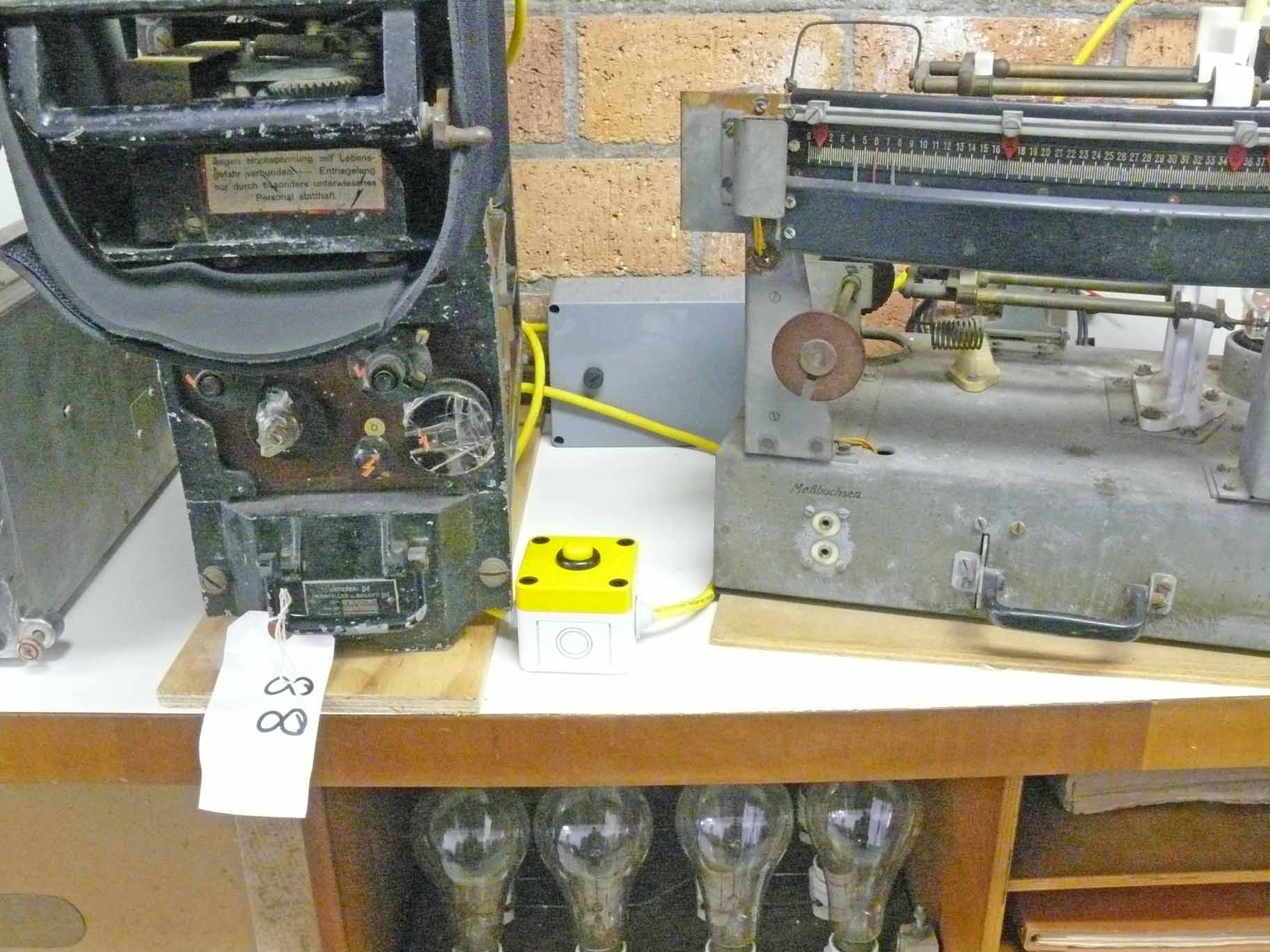
In front we notice the yellow button which has to be pushed-down as to activate the projection system. Please notice the way the rubber/cloth strip being wound around the frame in front
The advantage, is: that it safes the life-cycle of our most rare (delicate) projection lamp.
The grey box in the background holds the ring-core transformer; which, by the way, is having a (power) safety margin of 300 %.
As to increase safety, a quite clear way of indication that the transformer being still interconnected onto the mains, being provided.

Easy, because we normally pass through the alley and one's vision most likely will be attracted towards the red-light indicator, constituting the projection mains-switch

My wife Karin obtained on a local market a rubber/cloth sheet, well suited as to screen off light and also being stiff enough keeping its 'form' a bit
Both sheet ends being hold together by means of a 'Velcro' strip. The advantage is that the arrangement easily can be removed or fit together again.
The advantage, we do not interfere with the genuine status of this artefact.

Finally, looking at it from the right-hand side
The white label carrying '88' once constituted the auction lot number.
By Arthur O. Bauer
![]()