
Geheimschreiber repair problems
Currently I am feeling myself being in a deadlock
Being confronted with a huge bulk of technical problems and not knowing where it actually goes wrong
page initiated on 22 June 2013
Status: 26 June 2013
Let me first explain what the encountered problems generally are.
Typing in a text on the T52 keyboard - monitored on the (repeated) T52d text tape creates complete rubbish! However, this text being printed at the other end of the line, at the Siemens T68 machine, is received there entirely errorless.
The true table is showing that the regular telex code in Europe and the US was transmitted in a 5 bits code (although, in the US the baud-rate is not like in Europe 50 but 45.5)
The Siemens machine (as were the British Creed machines) operated in those days in a dual-current mode. Where Siemens operated + 60 V or - 60 V, whereas the most other systems used single current systems (0 and + 60 V or +48 V). However, the principle of coding is equal, which makes message exchange easy. The above true table is thus generally valid.
In what section goes it wrong?

Viewing the schematic of the Siemens T36Si machine, which equals the T52d electrically in respect to the receiver and transmitter section. Even the 'component numbers' are equal
Please click on the above schematic as to view it in PDF
Let us repeat first what happens when a telex signal arrives the telex apparatus

The data arrives at switch F 9
When this signal arrives it first triggers the electromagnet AME. This causes the selector switch (Empfänger) to start (executing) a single rotation. Successively F 10 followed by F 11 up to F 14 being closed for a few milliseconds. During this period the capacitors C 1 up to C5 being charged with the actual signal content (+ 60 V or - 60V) When this is being executed, via the contacts F 15 - F 16 up to F 19 the charge of C 1 - C5 being then uncharged over the 5 polarity-relays R 1 to R 5 successively (please notice the schematic below). Resulting in activating the Z or T contacts of the polarity relay (it will keep attached onto that particular contact until the next sequence).

Now, the decoder switch being triggered and following a special algorithm is executed such that when a closed circuit occurs the charge of C10 being used to activate the printer magnet DM (knocking from below the paper strip and just touching the type-wheel at the appropriate place and a symbol being printed); C 10 being by this means becoming uncharged. Thus when a second short circuit is found, C10 is still uncharged and a second printing is prevented for.
Just in between the two previous schematics the T52 machines implement the selector switch for clear text or secret messages (Klar - Geheim).
This is the advantage of the T52 top secret telex machines. Siemens did it electrically, whereas Lorenz could only cope by implementing in series to the telex in- and output line an additional mechanical unit known as: SZ 40 or SZ42 (SZ40/42). (S = Schlüssel, Z = Zusatz)
What might going wrong? The Empfänger section the decoder section (Übersetzer)? Or, in the line interface. As to stop having to deal with a chain of possible problems, I decided today to eliminate firstly the uncertainly whether the decoder is causing the problems.
First investigating whether the polarity-relays are interacting correctly with the character decoder (Übersetzer)

The five polarity relays still in place just before being removed. In the background looking at the receiver (Empfänger) switch

The polarity relays being replace by means of fixed cable wiring, now in such a way that only the character R is printed (wired according the true table below)

Viewing the relay base from what is accessible from above the chassis
'C' constituting the central polarity contact. Z representing the positive potential + 60 V and T at -60 V signal level.
When now fixed cables are inserted between:
R 1: C - T
R 2: C - Z
R 3: C - T
R 4: C - Z
R 5: C - T
the correct character 'R' is being printed. This will, of course, only occur when a start-signal being provided. There are two ways doing so, first by means of mechanically triggering (touching) the receiving electromagnet AME or by striking one of the keyboard keys.
I checked several characters and all worked faultless. We may thus assume that decoding section is operating correctly.
The conclusion is that the failure originates from a pre-stage.
What foreseeable options do we have further?
Viewing step-by-step from the decoder into the direction of the signals originating from the machine at the other side of the telex line.
Hypothetically, checking whether the lubrication of the clutches is causing transport instabilities. As telex signals consisting of 5 Bits, each one being transmitted in a particular time-window. I have an ambivalent feeling about this aspect.
Checking the receiver circuit. Consisting of the revolution of a cam-selector, which successively interconnects the signal input with one-out-of-five data-storage capacitors. These latter capacitor (C1 to C5), although once of the highest quality possible, look still good, though, should also be a matter of investigation. I personally, still believe that these are still performing correctly. However, in a thorough investigation this aspect should be checked carefully as well. What counts, is finding the easiest means possible doing so. When these capacitors are accessed the T52 machine has to rest at its back and this is most inconvenient, because the machine cannot be operated appropriately in this position. Special care should be taken, as to prevent leakage of oil clutch/gearbox.
The bottleneck is how to check the receiver? Bearing in mind that each of the 5 Bits may consist of + 60 V or - 60 V changing the sequence of the data-input line. It would be easy to supply all 5 Bits with equal signal polarity. Viewing the true table when - 60 V being provided during all bits - Baudot code number 32 is generated; which code is not dedicated. When all 5 Bits being + 60 V - code 29 is provided, which hardly can be checked as it only sets the keys in the text mode, without printing a character at all. We need thus an alternating 5 Bits signal code sequence.

The schematic of the our current Siemens interface (Fernschaltgerät 4-Draht)
Another failure source might be our current interface shown just above. Why and how, stays open. That we can monitor our T52d machine transmissions is only due to a special (optional) interconnection at the output of the interface. Where the transmitted signal being linked in a special way with the receiving input stage (still inside the interface unit).
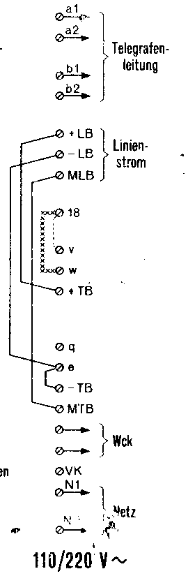
Interconnection between '18' and 'v' is the one making monitoring what is being transmitted possible
When the bridging wire between '18' and 'v' is removed the data input and output becomes entirely separated. Thus a four wire (4-Draht) system is capable of receiving and transmitting at the same time completely different messages! This is (normally) impossible for single current systems, where in most cases the transmitter stands in series with the receiver circuit, both directly correlated to one-another. What intrigues me, is the fact that under all circumstances the message is being received at the other end of the line (T68) faultless, whereas what is monitored after printing of the feedback text on our T52d is entirely rubbish. It might, however, have been introduced peu à peu, as I encountered at a certain moment increasing amount of errors.
During experiments early 1990s, I encountered minor problems which I then found being caused by temporarily drops (spikes) of the supplied voltages (+60 V and - 60 V). I therefore have this time implemented experimentally the more powerful power unit of the G-Schreiberanschlußgerät.
On 25 June I came up with the plan to disconnect some of the contact-wires (F 10 to F 14) of revolving the receiver (Empfänger) switch - in such a manner that some are getting + and other - voltage levels. Which should equal defined 5 Bit Baudot characters (all according the true table). By this means timing is being brought back to the actual timing of the internal revolving switch. Even when it would rotate irregular - the data is being handled errorless. Why doing it this way? Quite simple, because I would like to be sure that faults can be determined to a special stage inside the G-Schreiber apparatus first; and not that it originates from somewhere outside of the T52d.

I instantly went to the museum as to investigate whether this method works
Yes it does.
Fixed wiring caused that fixed characters being printed. I still have to go into this aspect. However, signs are indicating that the combination storage C 1-5 and the polarity relays R1 - R5 are also functioning correctly. Implicating that the new way of relay adjustment (partly visually and manually) performs better then the pure instrumental alignment.
I have not yet determined what actually goes wrong, but found several things which is asking for special attention. For example, cleaning the switching contacts more thoroughly as well as realigning all the switching contacts. Especially in respect to the contact gaps, which should be 0.4 mm. Visually is noticed that some might fulfil this value and others not.
It is also encountered, that it is possible to read some of the typed in text, but that all works best when a kind of 'cadence' is being maintained. This might also point into the direction of the clutch friction inside the gear box!
We might have to cope with a chain of various defects, which interactions are irregular.
It is also found - that the data storage capacitors C 1 to C5 are in a good shape. As decharging only occurred after my voltmeter made contact.
Hence, the most likely area of errors is found around the revolving receiver switch (Empfänger).
On 26 June 2013
I continued my headache project.
My first concern today was adjusting the free contact space of the receiver switch, which should be aligned at 0.4 mm.
Then I turned first my attention towards the option injecting straightaway a dual-current signal at line '47' of the T 52d apparatus (equals the T36Si schematic shown above)
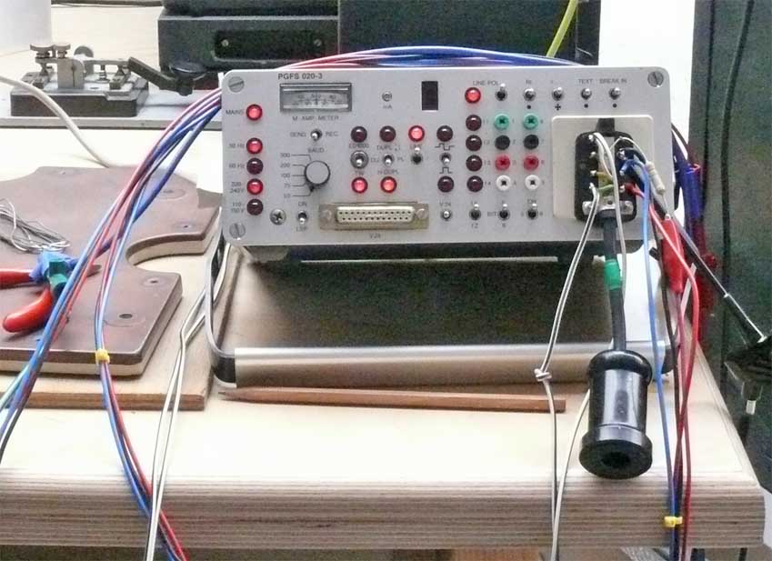
This telex tester on loan from Heinz Blumberg
It sadly is accompanied with a manual that is not giving full information and if so, not being full proof.
My aim was to follow the instructions according the manual. The two 60 V lines (+ TB and - TB and MTB) being wired accordingly. However, what is not provided is what the signal output connection is; it might be pin 6. Whatsoever, non of the 8 contact provided an output.
Then my attention turned towards the T52d again. Dick Zijlmans and I observed the result of my earlier contact adjustments.
It was noticed, that the repeated text acted more as it should be, though, still printing errors. These errors could be checked versus the true table. It was determined, that two bit responded incorrectly. Interchanging between the polarity relays of bit 4 and 2 proved that relay 4 was causing the errors. Replacement was the final step. All test is now being repeated correctly; Oh miracle!

The corpus delictum
Siemens & Halske relay type T43a
Visual inspection brought no failures to daylight (yet).
My new attention went on to the 4 polarity relay inside the Fernschreibanschlußgerät.

The 4 polarity relay are the ones with a vertical plate
Testing them each time against the relay of bit 4 showed in the T 52d apparatus proved that all four performed incorrectly.
We might have to wait for a new source of supply, because apparently the ones left over are all performing with errors.

After so much headache for a long time awaited our own typed in text can be monitored errorless
What have I learned today?
The well functioning of the polarity relays is quite critical and is essential.

It is a long time ago that we could print-out our typed-in test message correctly
To be be continued in due course
Please consider also: Geheimschreiber main repair project
Please also consider, or proceed with: G-Schreiber various docs
![]()