
Nachtfee survey page 3a
As to prevent our page 3 becoming too much overloaded, I have decided to add an extension page 3a
Page started on 25 December 2011
Status: 8 January 2012
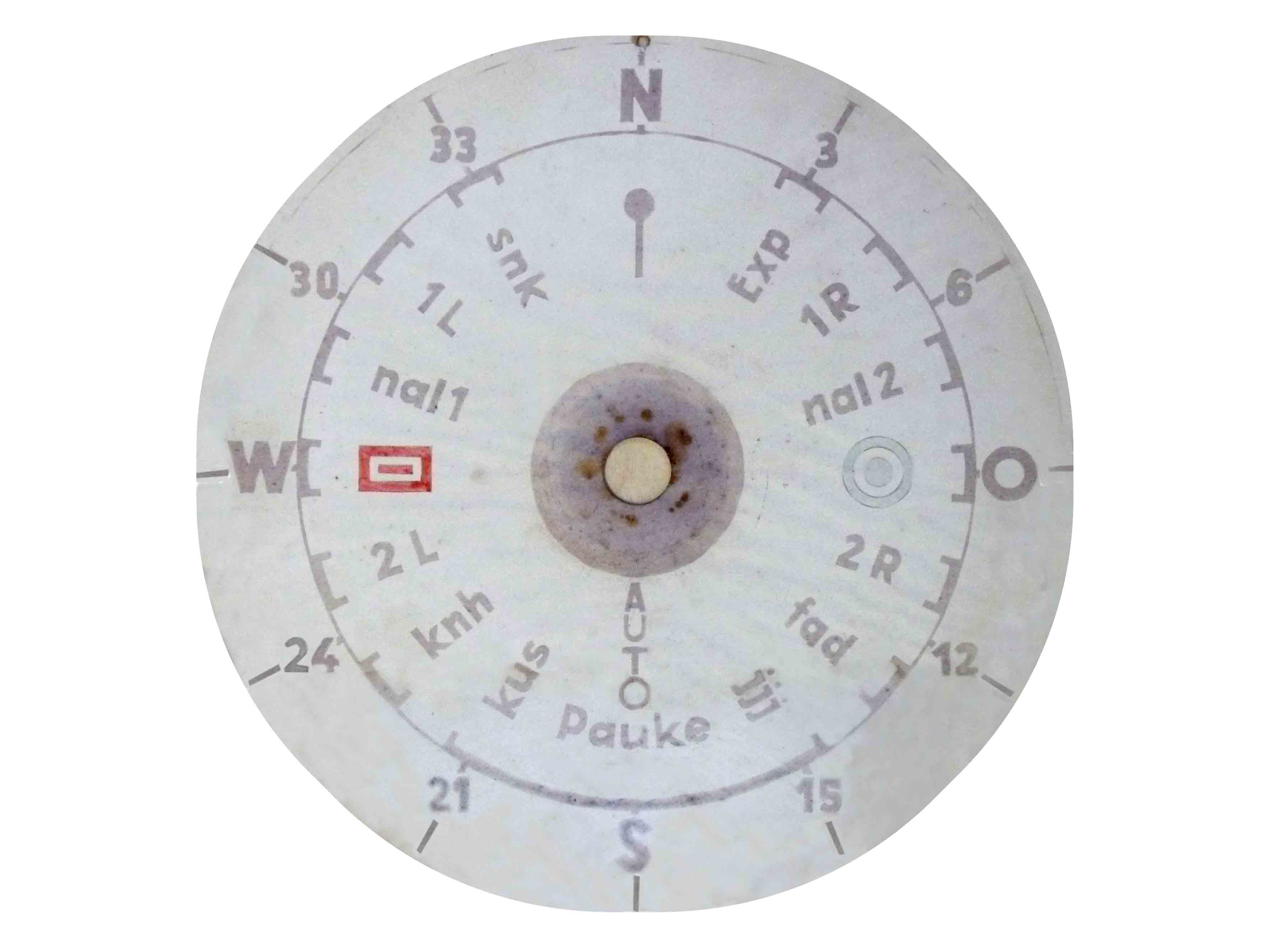
The occasion for starting up a new additional webpage, is the fact that we reached now the point where the 'Order or Command' scale is, after dismantling, mounted again in the Nachtfee main frame. Also the on quartz-channels synchronised module has been fit together within the frame again.
Bearing in mind how this scale looked like before please click on this hyperlink. It really is an improvement
You may think, why haven't you replaced this paper scale by a newly made version? I strongly believe, that as long as all scale aspects is recognisable, we should keep it as it actually is. Of course, showing the deteriorating aspects of its poor storage in the years passed. My wife Karin is, however, in the meantime working on a Photoshop version, as to to obtain the best reproduction possible. Entirely based on the photographic reproduction of the scale shown below. Of course, it has been reproduced photographically without parallax and other errors.

The 'Corpus delictum' being mounted on the Perspex (Plexiglas) 'order' scale. The two pointers being fit together again. As usually in such case, both had several times to be demounted, as something should have been fit together differently
This ring caused the damage done. The paper scale was in some sectors just a bit too big and was touched (pressed) by this metal ring. The interaction between the hygroscopic paper scale and the metal ring caused rust. The ring itself was only showing signs of rust just where it had been in contact with the scale paper.

The next step was mounting the 'order compass' at its appropriate place again. Sometimes a difficult undertaken, as so many factors have to be kept under control; and a human being is only gifted with two hands

After the 'order system' has been fixed partially, the scale-lamps-mounting has to be connected again

The 'order assembly' is in position

Günter Hütter was so kind to provide a LB2 with integrated Al. mounting. Please notice the two small lamps on either side of the LB2 mounting. What I never have realised before, is that the two slits in the Al. mounting ring is providing a kind of scale illumination. I thought firstly, that it would necessitate an additional 'scale-disk' but apparently it illuminates the engraved black lines of the CRT screen
We are now reaching the point where we are putting first 220 V ac on the Nachtfee main chassis. Though, without HT.
Please consider also my brief Survey Report, which notebook pages are regularly upgraded

The Nachtfee under test. Please notice that the quartz-channel section is being integrated again
For convenience the power supplies and other equipment is mounted on a movable table. The yellow/grey apparatus on top of the variac is a HT power supply (Radford Lab.) providing 0 - 6 kV at max. 3 mA. Incorporated only for allowing controlled HT for the two CR tubes.

Measuring at the EL11 stage, which works as expected
We have now inserted an EL 11, which I guessed is the only option regarding the valve connections and the physical space provided. My estimation was correct. And at the anode of the EL11 we saw a saw-tooth of 200 pp at the oscilloscope. I sadly forgot to take a screen shot. But the stage works!

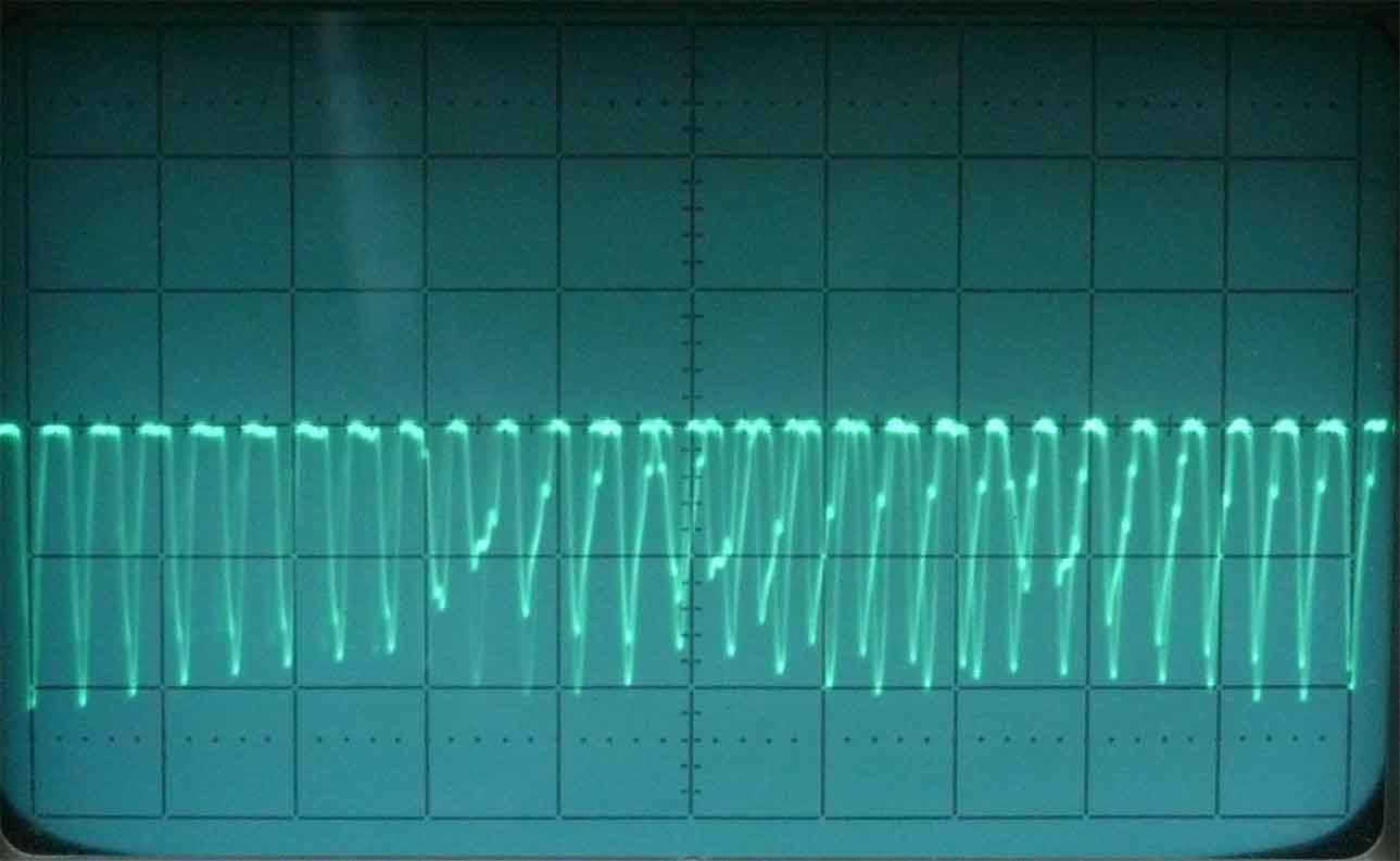
This oscillogram measured at the anode of Rö 10, is for me the first sign which shows an interaction between what is shown at the scope screen and the actual pointer vector setting at the 'order compass'! (the stage is, when we look from the front-side, on the right hand-side of the big CRT screen)
What we see on this photo differs a bit different from what the human eye is experiencing; when he looks at the CRT screen, due to the long exposure time of 1/6th of a second (using diaphragm 8). According the time base setting the pulse is repeating itself about every 20 ms.

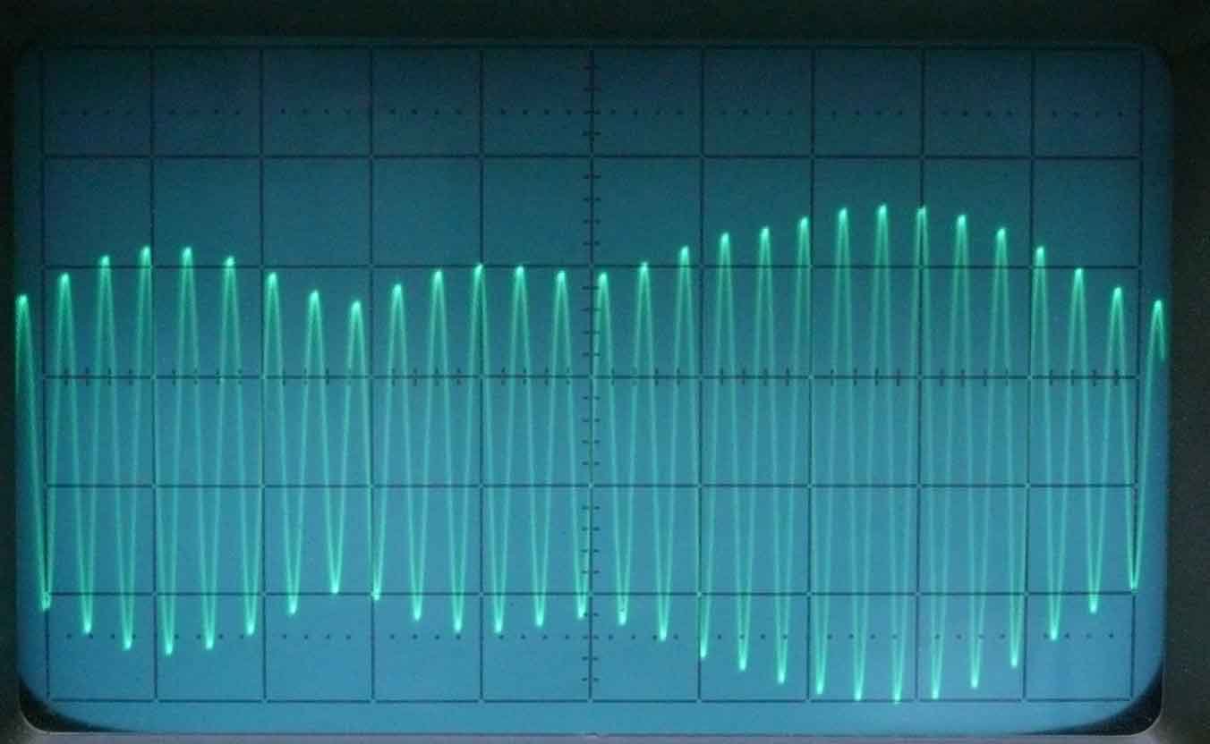
Maybe this graph is better understandable, again pulse repetition is 20 ms
On 27 December 2011
we continued:

The position of the valves in the top section
The left hand section - the centre section and the right hand section

Top view like the previous one

The centre section

The blue and red capacitors are bridging the partially disconnected 'block-capacitors'. These types often fail owing to hygroscopic phenomenon of the dielectric. Causing quite some electrical loss and, hence, getting heated. They often constitute a rather low resistance

Viewing on the left valve sockets for Rö 20 and Rö 21. On the right in the background is valve socket 19 for the high tension rectifier (I guessing type RFG 5)
The two transformers on the right are concerned with the about 1 kV supply.

The saw-tooth amplifier EL11 and its driver RV12P2000

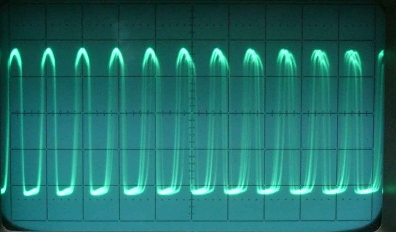
Signal measured at the anode of EL11, just at terminal 1 of its output transformer
Curious, is that I have not yet found where this signal is provided to. Its amplitude is about 175 Vpp

First proof of my estimation that the positive side of the HT for the CRTs is being connected onto ground. Consequently, the cathode is then to be kept at about - 1 kV
This is done as to keep the potentiometers for controlling beam spot position at a low voltage level against ground.

Signal at the g1 of Rö 1, without quartz-channel being selected
Signal at g1 of Rö 1 with a quartz-channel selected
Signal Rö 2 measured at the anode
Signal measured at the anode of Rö 4. It doesn't matter whether a quartz-channel is selected or not

Signal at g1 of Rö 5. An interaction is visible when the 'Phase' setting is being rotated. Its setting is also linked to a servo (master) (sometimes called Selsyn) or Drehfeldgeber as the Germans call them. Please notice, that all three servos doesn't have a slave drive, but all is interacting electrically. I suppose that the servo rotor is acting as a goniometer inside a three phase stator

At the anodes of Rö 5 and Rö 6 is about the same kind of signal provided
After the left hand side I turned my attention towards the central section. Not yet knowing what its function actually is.

At the anodes of Rö 12 and 13 I discovered that there doesn't exist a signal at all. The cathode both had the same high voltage of about 80 V. They apparently are functioning in push-pull
Following the circuitry, at the lower end of the cathode resistors of 1.5 kΩ there still was about 80 volts. Thus they weren't acting as a cathode-follower. Then I saw a not connected small piece of wire and I figured out what might have been the most likely point to contact at. My guess proved to be correct.

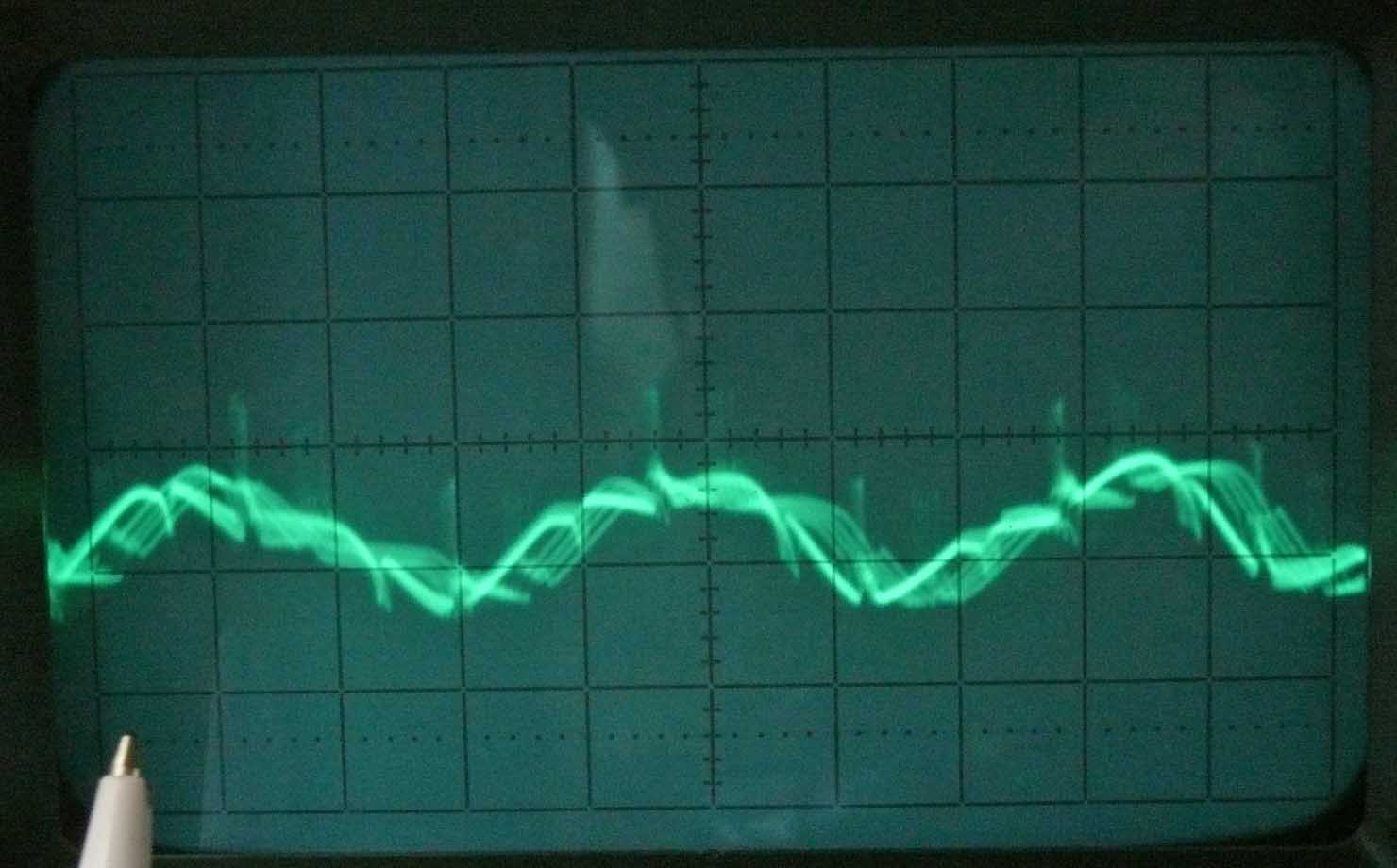
With some imagination is it possible to see that the lower trace is indicating the existence of a sinusoidal signal
It is not yet know how the screen presentation should be. From the controls at the front panel, one gets the impression that it should be a circular presentation. Maybe at least a single circle is to be painted.
Consequently, it might be that the vertical deflection system is lacking sufficient signal.
The time-base thus works

It also was found, that the lower time base deflection (length) interacted with the 'order compass' setting as well as with the unknown control (both linked internally with a servo drive (Drehfeldgeber)

Both 'Phase' and the unknown controls are being mechanically linked onto a servo motor. Although, doesn't acting in this way

The lower trace is responding on some settings of the 'order - phase' and/or the unknown control. Sometimes the trace shrinks and after some time it comes up again, sometimes after a while disappearing again
An unexpected finding was the application of some double geared potentiometers

The double potentiometer-gearing is meant for controlling both independent cathode ray sections (keeping them in concert)
For with only a single control to be adjusted for both luminance and beam focussing. As we may expect that both CRT systems are about identical.
One of the considerations of taking off the two front panel plates was, that from inside I had already noticed the existence of two curious potentiometers. Another thought was whether it is possible to demount or opening the 'Frequenzkontrolle' push-button-switch'. Which is found to be a bit complicated, albeit with no doubt should be repaired. Also the broken handle of the Freya-Polwender selector has to be replaced; which is a most inconvenient job! As it is hidden inside the least accessible compartment (section) of the Nachtfee chassis. Also having quite some soldered contacts and wires (having minimal wire lengths).
On an additional occasion op 29 December, I was able to spend a few hours extra in the Klooster and was looking further into the Nachtfee survey.
I was still intrigued by the fact that we didn't see anything on the LB2 screen (the one above the 'order compass'')
I guessed that there might be something wrong or failing around the deflection circuitry of the LB2 CRT. This so-called "Polar-Kathodenstrahlröhre" , which is build in a way that the signal trace is deflected around a conical cylindrical cone and an outside (conical) cylinder.
Then my eyes were attracted to a 2 µF block-capacitor hidden at a difficult accessible place (I would like to say, of course). As they all tend to be faulty, I electrically bridged it with an equivalent capacitance. And this seems to lift some of the problems. A part of an ellipsoid is now visible:

The centre section is kept in the shadow of the centre cone
Please notice also the soft light illuminating the CRT screen, the left small alamp has to be replaced, in due time.
I also discovered that the EL11 stage actually is providing the saw-tooth for its magnetic deflection. The next step should be: finding out why the horizontal deflection component is faulty. However, there exist a small amount of it, as we otherwise would have had a straight line only.
These facts, combined with closer investigation of the double beam CRT deflection stage, is telling us that what was assumed previously is not correct. The double beam scope has to have a normal A-scope like presentation. Thus, acting around a horizontally deflected line. That we thought it was differently, is caused by the circumstance that next to it is a control called "circle diameter" (Kreisdurchmesser). It was found, that this control directly interacts with the LB2 deflection amplitude.
Also the 'Frequenzkontrolle' push button starts to function again after having sprayed it with 'Kontakt 60' fluid. Although, it sometimes does fail a bit, but I hope that using it might lift this nuisance.
Nevertheless, replacing the 'Freya-Polwender' switch is causing me still headache! Because its wires are kept very short and also is being fit at a very small and inaccessible place.
On 2 January 2012
We continued with investigating why the LB2 deflection failed
It was found that it was my own fault, as I had bridged a 60,000 pF by means of a 6,000 pF sample. After having put two capacitors of each 0.12 µF in series I checked against a Wheatstone bridge and it constituted, within a few hundred pF 60,000 pF. (this is done as to double its working voltage.

For the first time the control CRT was showing a more or less circular painted trace
That the trace is a bit blurry is caused also by the fact that a quartz (channel) signal is interacting with the about 970 Hz signal.
I have been thinking, couldn't it be, that what is measured as being about 970 Hz should actually be a 1000 Hz signal instead? This would make locking onto the about 15,000 Hz quartz signal more likely?
Queries, all the time new queries!

The LB2 display is showing the existence of the on a quartz synchronised signal (point 3 of the final output of this module, see the notebook report pages VIII - X)
The handle just under the LB2 screen (partly visible) is to compensate for the distorting value of the locally existing earth-magnetism.
That the painted trace is a bit blurry is originating from the camera exposure time versus the (LB2) time base frequency.
A major encountered problem, is that we have to deal with many variable parameters, and not knowing how they should interact.
For instance, the push button "Frequenzkontrolle" (frequency check) is working again. It is now clear, that what had been designated as being the Nachtfee signal output actually proves being a 'pulse signal input' line. What kind of pulses do we have to deal with? One of the next steps will be trying to simulate a variety of square wave pulses, and watching how the Nachtfee circuitry is responding.
Another point of attention is, why is the amplitude of the signals painted at the two CRT screens so low? It has become apparent, that in the past someone has tried to change settings of the two ceramic trimmers which constitute pulse amplitude and brightness for the LB2 display. This is a quite common ceramic trimmer fault, but one should approach them carefully, but laymen is not aware of this downside.
It was also found, that there seemingly are more block-capacitor-like modules. Again, what they actually are and what their value eventually should be is also an unknown factor. Are they eventually a choke instead?
It was also possible, to find out what the output transformer of Rö 3 (EDD11) is. It proved to be a pair of transformers. Difficult to distinguish how these are interacting and being wired. All these kind of modules is having 6 equal connections, that is all we know. One is becoming rather desperate tracking the inter-wiring! A most difficult job! Bearing in mind, that there are many modules of which some are block-capacitors the rest being housed in a quite small Al can having six connections. Most hampering is that these cans are being fixed against the chassis by means of iron strips, but the screws are only accessible from where the big CRT screening tube is fit. It is, however, out of the question removing it. Thus we have to cope with many uncertainties.
At a certain moment, I heard a weak buzzing noise, which finally proved to be one of the 8 'Jahre' electrolytic capacitors of 16 µF. Although, these are wired with the HT circuit, their mutual ground is kept open from the Nachtfee chassis. My guess, some of the voltage drops over the many voltage dividing resistors is causing it. My remedy was, cutting its connection, but leaving a small reminding wire, as to remind me how its connection had been before.
On 3 and 4 January 2012
We continued our Nachtfee Survey
My first focus was looking more in detail around the LB2 circuit section

This curved plate had first to be removed, as to allow access to the mall functioning trimmer, which is a well known fault; caused by too heavy friction between the fixed silver layer and the rotatable ceramic trimmer disk, caused by a kind of crystallisation
Normally a kind of heat shock, accompanied with some mechanical force, might cure it. But someone in the past has with some uncontrolled force broken the solder-contact between the upper silver layer and the central tuning screw.

The right hand trimmer is mall functioning
We luckily have had the vision buying a bag full of them, a long time ago. I only replaced the faulty sample. Though, what is also important, is that we discovered two tar-roll-capacitors, which doubtless should be disconnected and being bridged by good quality types.

Closer photo of the section
The metal cylinder is the housing of the magnetically deflected LB2 CRT. Until now, all Siemens & Halske resistors proved being still within their tolerance value. Remarkable after > 66 years.
What already was expected, is that what was thought being a coaxial output cable, actually is an input one. Its input potentiometer is marked 'Impulsamplitude' meaning pulse amplitude. What is more likely feeding this line with a square wave signal?

The setup with our Wavetek pulse generator. Frequency is measured by our DANA 1998 counter. What we read here is with 5 digits after the the dot. We normally use a 1/10 of a Hz resolution. Please notice also the pulse which is quasi synchronous at the time base line at the LB2 control screen (about at 40 minutes)

Owing to camera exposure time versus frequency difference of the LB2 time base, the screen is showing the rotation of three blurry signals (impulse signal being three times higher). There doesn't exist any kind of influence of the 'small order pointer'

A single pulse is shown at a pulse recurrence frequency of 259.4 Hz
We may assume that this is equal to the time-base frequency. Again, facing the too long camera exposure time.
It is also discovered that the internal frequency source is not very stable and that at some time we obtained quasi synchronism at a few Hz lower like (254 - 256 Hz)

Maybe the best screen shot of a painted 'single pulse' of this series
It was also found, that quasi-synchronism existed only as long as a quartz channel is selected. When it was switched off the painted circle shape as well as synchronism totally failed.
We encounter some strange problems with the quartz oscillator modules, as only a single one works. Some had worked before, but are failing now as well. Module number 5 is constantly failing. We also upgraded some other units, but these all fail. Why is unknown. When the good one is inter changed with any other position it works. I know from previous experience, that handling quartz oscillators of very low frequency, one should take great care to its circuit design. As they should starting up very softly. The Q-factor of these kinds of quartz devices might be >100,000! When their amplitude is becoming too high they will be destroyed. This may have been the reason why each oscillator module is having a special potentiometer. Of which I believe it should be starting up in position 1 and then the closed loop-gain should be increased; this procedure can be checked at both CRTs when you push the 'Frequenzkontrolle' push button. In theory we say the the loop gain of an oscillator is 1. Although, in some RC oscillators the loop-gain is often > 29, as to obtain an oscillation condition where the loop gain is 1.
That the front slope isn't sharp might be caused by the way we are injecting the voltage onto the Nachtfee List-Stecker connector (in post war days copied and adapted by Amphenol in the US and the Russian as well). For safety reason, I have inserted a 1000 pF capacitor. We certainly face also a mismatch between the Wavetek output and our BNC cable and the original German (Vacha) coaxial cable. Also the way the signal divider (potentiometer) of the Nachtfee apparatus is causing an amount of mismatch.
After we have replaced the two capacitors hidden left from the LB2 housing, the painted trace on the screen showed improved circular shape.
It was also noticed, that the formerly measured saw-tooth deflection signal at the anode of the EL11 has changed into a quite good sinusoidal like signal. Which is necessary for a linear circular time base
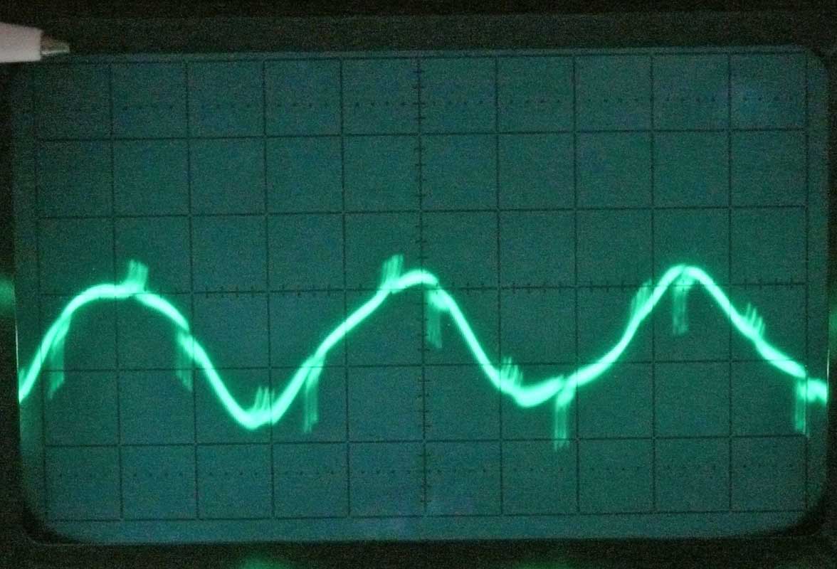
Signal output measured at the 'Freya-Polwender' output. The spikes are not well visible due to the long exposure time of our camera. Order pointer pointing East (O)
My pen is used as to recognise which screen shot is belonging to what section lines of my Nachtfee survey report

Order pointer facing West (W)
Oder pointer facing between East and South
It was also found that pulling out valve Rö 6 the EDD11 changed the Freya-Polwender output such that its sinusoidal signal increased up to 30 Vpp, but lacking the spikes information. This valve stage consisted also the failing EDD11, which is thus fully in accordance with our previous observation.
What the Germans designated 'Freya-Polwender' is, is that by means of a double-pole-switch the two signal wires are interchanged.
Please follow more in detail my brief notebook report
We have reached now the status where our Nachtfee system and investigation is becoming fruitful and is beginning to act in a way as it was suppossed to respond during wartime days.
Please continue with our dedicated page:
Please don't forget to use the handsome: Nachtfee Chronology page
And, the PowerPoint progress page (converted into PDF)
By Arthur O. Bauer
Please consider also our Nachtfee discussion page (status: 5 January 2012)
Please go back to, or proceed with: Nachtfee starting page (status: 17 December 2011)
Please go back to, or proceed with: Nachtfee survey page 2 (status: 8 December 2011)
Please return to, or proceed with: Nachtfee survey page 3 (status: 21 December 2011)
Please go back to, or proceed with: Nachtfee MLK Lab. Survey (status: 13 December 2011)
Please go back to, or proceed with: Nachtfee Inbetriebnahme (status: 2 February 2012)
Please go back to, or proceed with: Nachtfee evaluation and conclusion page (status: 6 February 2012))
Please consider or go back to: Nachtfee FuG25a project - investigating how the Nachtfee data was conveyed towards the aircraft display (status: 18 February 2012)
Please go back to, or proceed with: Handbooks papers and product information
![]()