
The V 1 gyro platform
survey
I would like to state firstly, that I do not like weapons myself. My interest is dedicated to the history of technology.
Leading often to an intriguing reversed engineering survey.
Initiated on 2 June 2013
Status: 9 June 2013
Please consider also our new page showing a script made for a semester examination in 1970 on the theoretical aspects of controlling such a flying platform
This artefact was recovered in June 1945 from a crashed V 1 near the village of Holten.
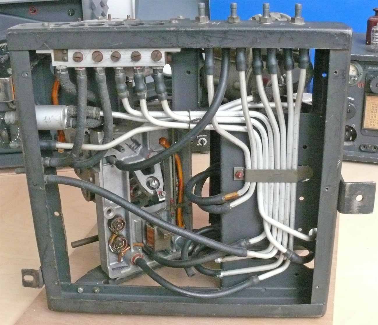
Viewing one side of our V 1 gyro platform
On the right-hand side we see the system timing unit (Uhr). On the left-hand side we notice a gyro (Kreisel) which I, with my current knowledge, would like to designate 'Lagekreisel'. It is likely that it was triggered by means of a barometric height information*, it could however, as we will see later also be triggered electrically by means of activating an electromagnet.
* It is know understood, that the barometrically controlled system is tilting the Lagekreisel platform entirely. (when it is unlocked)
Studying this photo more closely, it is becoming clear to me, that the electrical cable once was connected onto a 'List' connector which was fixed by means of 4 screws, the cable connections entering through the quite wide breach symmetrically in between the four screw holes. It is also likely, that the open wire ends attached to the timing mechanism )clock) was also cut from the List connector separately.

Viewing in my understanding the two horizontally orientated gyros such as 'up-down' and 'left-right'. In the background with the red circular scale a barometric setting. That it actually concerns a barometric system is a guess, as its scale goes from 750 - 1050 most likely standing for millibar
In the Wartime instruction film (P 3) is noticed that the gyros ran at about 30,000 rpm (500 rotations per second)!
This entire V 1 steering system (and gyros) was powered pneumatically.

Please notice the the right-hand gyro is having a horizontal rotation axis, whereas the left-hand gyro is providing a vertically orientated rotation axis. On the far left we have a better view at the barometric scale, which is activating a pneumatic cylinder. Although, not well visible, is a missing leaver, which most likely has to un-lock the what I designate 'Lagekreisel'

Viewing the Lagekreisel (gyro) from a different perspective
On the left-hand side we notice two kinds of 'fingers' with in between a disc sector which is mounted on the gyro axis. My guess: the two fingers once were part of two coils each one at a finger, the arc change of the (sector) disc is influencing the flux interactions of this system*. Whether as to damp its movement is not yet understood. But, the three wires just visible points in the direction of my presumption. The handle on the gyro left-hand side is to lock the gyro axis into a forced position, which can be un-locked by means of the barometric system as well as by means of an electrically controlled relay.
* See the two coils below on the left-hand-side of the gyro

Viewing particularly the two fingers (part of an eddy current system?)
I have not yet checked whether these finger by their own means possess magnetic properties. My presumption, however, is that two electrical coils were once involved.
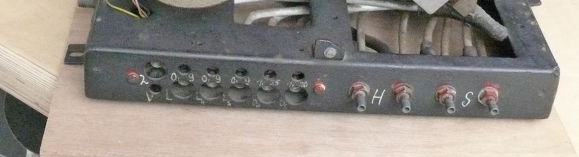
Viewing most of the the pneumatic in- and outlets
H = Höhe (height)
S = Seite (left - right)
L = likely 'Lage'
λ = ?
V or υ ?
Maybe that we can borrow a genuine manual and the uncertainties being lifted.

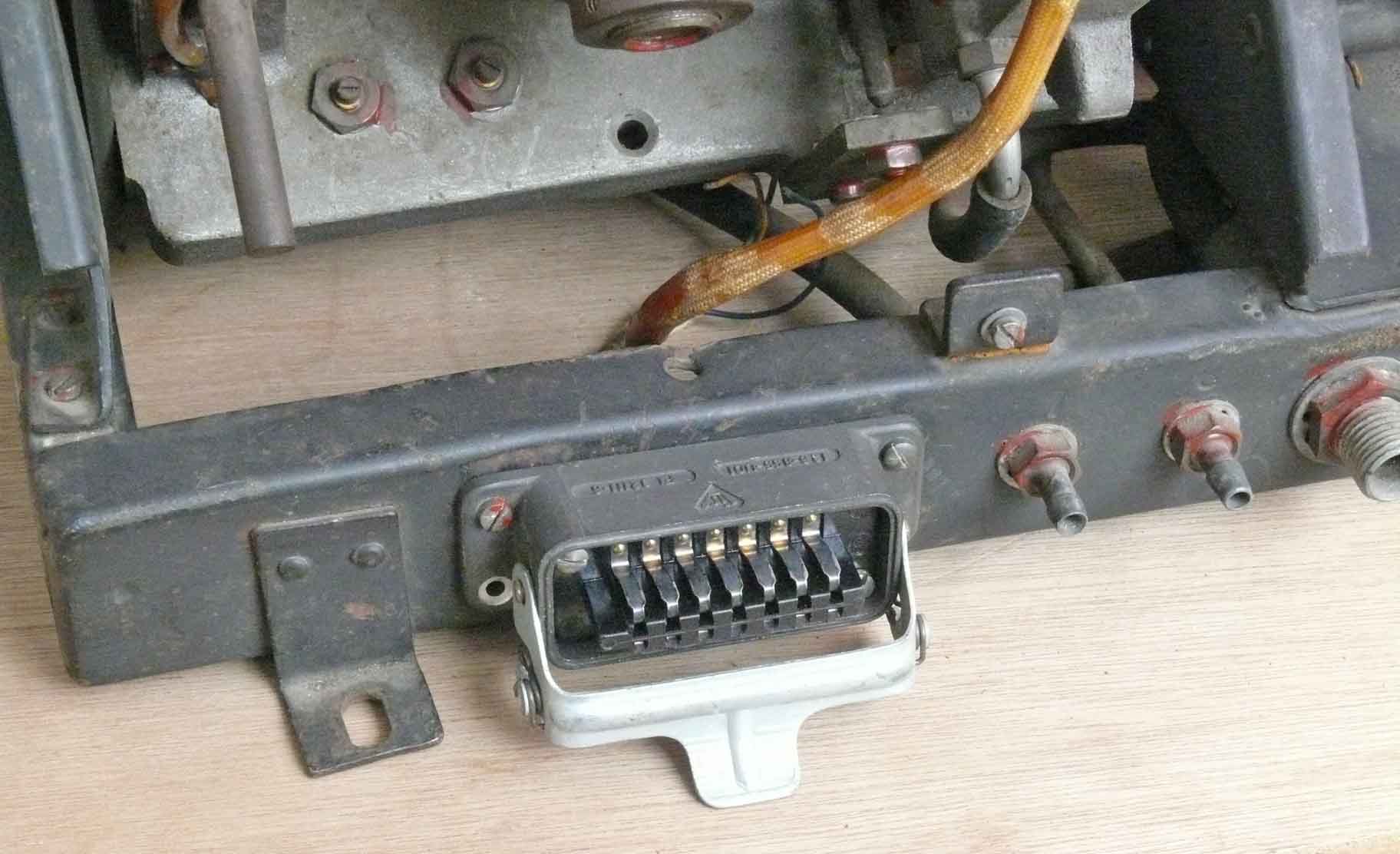
According this information it concerns: 127 - 8027 03
127 most likely is the GAF group serial number and 8027 might be, like practised in most other cases, being a drawing number. Where 03 stood for I do not know. The two small drums most likely had to damp the movement of the gyro axis.
According Peter Aichner's Funkbase on 'Luftwaffe-Ausrüstungsgeräte' the 127 - stood for: Kursgerät, Kurszentrale .... On page 14 is given: 127 - 8027.02 Steuergerät für V 2 made by Askania. Our apparatus doubtless belonged to the V 1 system, the V 2 operated electrically, whereas the V 1 controlling system operated (mainly) pneumatically.

On the right-hand
side the barometric controlled system, which at its plunger-shaft end (on the
left) has a lacking arm. This arm was constructed likely in a manner the at a
certain position it could push the circular disc just in between the controlling
clock and the barometric system. When this disk is being pushed inwards it
releases the so-called 'Lagekreisel' proving freedom as to act gyroscopically
The arm was according the wartime German instruction film (P 3) tilting the entire Lagekreisel platform. Please see the next screen shot photo.
This subject needs, of course, attention; though as long as we have no further documentation the query should be left open.

On 5 June new YouTube films being implemented and I took a 'Print screen shot' (YouTube link P 3) which shows clearly how the missing leaver arm is interacting with the Lagekreisel platform

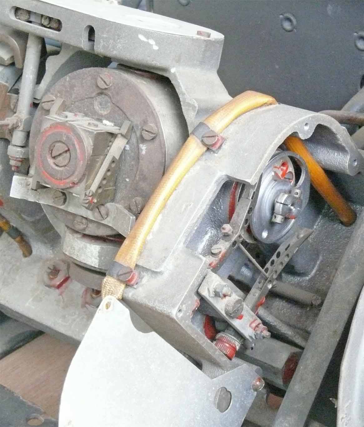
Viewing the mechanism more closely
It is astonishing that the rubber tubes are still in such a good shape. This is due to the fact, that the Germans used synthetic rubber generally know as - Buna.
Also the Al tubes are seemingly without signs of oxidation

This detail has been photographed for two reasons. First showing the BAL 2282 number, which stamp was dedicated to a special person, who carried the responsibility of its official acceptance. Secondly, W 853900 might be a production number
BAL = Bauaufsicht Luftwaffe
Considering the BAL stamp visible on the first photo of this page, it is evident that the main chassis is being accepted by someone else, as the number is only consisting of three digits instead of four.
We are no expert on this particular subject, and maybe some of the webpage visitors have access to accurate information on the production of the V 1 components; whether made near to Nordhausen or elsewhere.
Please come forward and share your information with us!

For this occasion closing with a detailed picture of the controlling timer or clock mechanism
(Click on B to return)
The lowest text: Bei direktem Zielkurs Zeitmarken auf 0 stellen Kipphebelstellung gleichgültig (most likely pointing to the upper Links - Rechts switch handle).
Drehzeit sec. (running time?) Curious, because in German language they abbreviate seconds in 'sek.'
Vorlaufzeit in minutes or seconds
Widerstand means restistor
The text to the centre hole: Aufzug; which points to 'a spring loaded winding up' mechanism
On 3/4 June 2013
I used the opportunity to day to take some additional photos. However, going this time a bit more into the system details.
My first first aim was to look what is behind the two Al covers around the Lagekreisel. Maybe not good visible, this system is controlling the vector of Lagelkreisel mounting frame
It is clear, that an eccentric disk is repeating the actual vector angle of the Lagekreisel. This is actuating a miniature regulator which is influencing the air pressure fed onto the gyro system. The arm is moving slightly either side.

My next point of attention, what is inside the second attached box?
This system is actually responding at the spinning angle deviations. Likely keeping it in a position of an equilibrium.

This photo shows the actuated situation of the previous non actuated condition. Please compare this situation with the previous one

This photo nicely shows the way the Lagekreisel platform is to be locked; when the locking pin enters the hole of the gyro. The system can be unlocked in two ways, one electrically by activating the electromagnet or, by means of a push bottom right of the timing clock system (Please notice A)

Viewing the locking hole in detail
For it the gyro body should be rotated 90°, before locking is possible.

After removing a small cover an electrical contact becomes visible, which is indicating (repeating) whether the Lagekreisel platform is locked or unlocked

The other way unlocking the Lagekreisel platform is pushing the spring loaded disk inwards

The Lagekreisel platform visibly being locked. It can be unlocked by means of an electrical pulse activating the electromagnet, or by means of the previous shown push mechanism which is mechanically pushing the spring loaded lock towards the electromagnet core and by this means unlocking the platform
The small electrical wires are insulated by PVC means, recognisable by their bright colours.

Look please closely on the left-hand side of the gyro axis for the ventury air outlet, which is influencing the amount of air flow entering the hole.

Viewing the damping mechanism which is responding onto the 'rolling' of the platform
According the further down shown YouTube films (P 3) this gyro was to control the horizontal axis (Querruder) which steering air outlet is marked 'S'

Viewing the second gyro, which according YouTube film 'P 3' is to control the horizontal flight path and designated at its steering air outlet 'H'
I don't know yet how this gyro
platform was mounted inside a V 1, it is therefore yet impossible to determine
which gyro is doing what.
Please notice the YouTube films below
It is also not yet understood
where the electrical connections onto the periphery is being provided.
Please view for it the screen dumps below
On 5 June 2013
As a matter of informing those of whom might be interested in this subject, I also informed Bill Bogdan; he very kindly responded and he passed on to me an interesting hyperlink series which is worth viewing at.
Please notice:
I would like to stress again, that weaponry is not my 'piece of cake'! However, dealing with techniques in an imaginary historical context is like studying the content of an empty box. The application of techniques may increase understanding of what it actually was or is about. Not neglecting the aspects of Human Sufferings!
The next film links will bring you in touch with genuine German instruction films; most likely made for those engaged in this project.
Part 1: http://www.youtube.com/watch?gl=NL&v=ffjdgVU_RMQ&hl=nl
Part 2: http://www.youtube.com/watch?feature=endscreen&v=NXWSQ4clh7k&NR=1
P 3: http://www.youtube.com/watchv=HQccOvNG_ZY&feature=endscreen&NR=1
Part 4: http://www.youtube.com/watch?v=-XiRkk4zYtU&feature=endscreen&NR=1
Part 5: http://www.youtube.com/watch?v=sfN50qB6h8Q&feature=endscreen&NR=1
Please notice in the next film that the recordings of the V 1 flying movements were taken by means of an Askania Theodolite (some with a build-in timing watch)
Closing with a British film on the military application of the terror weapon
By means of the computer option 'print-screen' on my keyboard was it possible to freeze significant pictures.

On the left-hand side we see the dual-coil arrangement (missing in our sample) and on the right-hand side the electrical cable connections, which is lacking at our apparatus too
Bearing in mind this photo it should be possible to find signs of its existence.

The 'List connector' and the two cables are good visible. On the right-hand side we notice the cable connected onto the timer module (clock)
This photo clears the query how the V 1 gyro platform was electrically interconnected with the V 1 system

Viewing the gyro platform with its cover mounted inside a V 1
On 6 June 2013
Bill Bogdan very kindly did send me a bunch of additional photos, apologising for that - had he known that eventually these should be reproduced for educational purposes, he surely would have given more attention to their quality. In my perception, these are good enough and a selection of two were made as these match exactly on to some of the open queries.
He commented additionally, that photographing was being hampered because the artefacts were shown in a glass display.

V-1 autopilot on display at the Udvar-Hazy branch of the NASM in Washington Museum.
Showing a similar gyro platform as ours.
What intrigues me, is the quite good vision of the way the barometric controlled leaver arm is being linked onto the Lagekreisel platform.
It has now to be decided: what should be done?
Making a replica of these missing parts? If so, these should then be marked additionally as to indicate that it do not belong to the genuine artefact on display.

This colour photo shows the missing coils nicely

Combining both photos, I went to the Museum premises and viewed where the screw hole is. The red screwdriver is marking it
I also used the opportunity to mount, albeit temporarily, a List-Stecker
A List-Stecker mounted where it once had been
Whether it should stay there is to be decided later.
9 June 2013
On 8 June, I visited my good friend again and he showed me a genuine flyer recovered from a V 1, which once did crash at the Posbank near to Arnhem. This flyer is in my perception rather interesting and unique; I therefore decided to dedicate a special web page for it. Please click at: V 1 flyer
To be continued in due course
By: Arthur O. Bauer
![]()